Just a second! 🫷 If you are here, it means that you are a software developer.
So, you know that storage, networking, and domain management have a cost .
If you want to support this blog, please ensure that you have disabled the adblocker for this site. I configured Google AdSense to show as few ADS as possible – I don’t want to bother you with lots of ads, but I still need to add some to pay for the resources for my site.
Thank you for your understanding. – Davide
One of the most common issues we face when developing applications is handling dates, times, and time zones.
Let’s say that we need the date for January 1st, 2020, exactly 30 minutes after midnight. We would be tempted to do something like:
var plainDate = new DateTime(2020, 1, 1, 0, 30, 0);
It makes sense. And plainDate.ToString() returns 2020/1/1 0:30:00, which is correct.
But, as I explained in a previous article, while ToString does not care about time zone, when you use ToUniversalTime and ToLocalTime, the results differ, according to your time zone.
Let’s use a real example. Please, note that I live in UTC+1, so pay attention to what happens to the hour!
var plainDate = new DateTime(2020, 1, 1, 0, 30, 0);
Console.WriteLine(plainDate); // 2020-01-01 00:30:00Console.WriteLine(plainDate.ToUniversalTime()); // 2019-12-31 23:30:00Console.WriteLine(plainDate.ToLocalTime()); // 2020-01-01 01:30:00
This means that ToUniversalTime considers plainDate as Local, so, in my case, it subtracts 1 hour.
On the contrary, ToLocalTime considers plainDate as UTC, so it adds one hour.
So what to do?
Always specify the DateTimeKind parameter when creating DateTimes__. This helps the application understanding which kind of date is it managing.
var specificDate = new DateTime(2020, 1, 1, 0, 30, 0, DateTimeKind.Utc);
Console.WriteLine(specificDate); //2020-01-01 00:30:00Console.WriteLine(specificDate.ToUniversalTime()); //2020-01-01 00:30:00Console.WriteLine(specificDate.ToLocalTime()); //2020-01-01 00:30:00
As you see, it’s always the same date.
Ah, right! DateTimeKind has only 3 possible values:
publicenum DateTimeKind
{
Unspecified,
Utc,
Local
}
So, my suggestion is to always specify the DateTimeKind parameter when creating a new DateTime.
In this article, I will show you two simple tricks that help me understand the deployment status of my .NET APIs
Table of Contents
Just a second! 🫷 If you are here, it means that you are a software developer.
So, you know that storage, networking, and domain management have a cost .
If you want to support this blog, please ensure that you have disabled the adblocker for this site. I configured Google AdSense to show as few ADS as possible – I don’t want to bother you with lots of ads, but I still need to add some to pay for the resources for my site.
Thank you for your understanding. – Davide
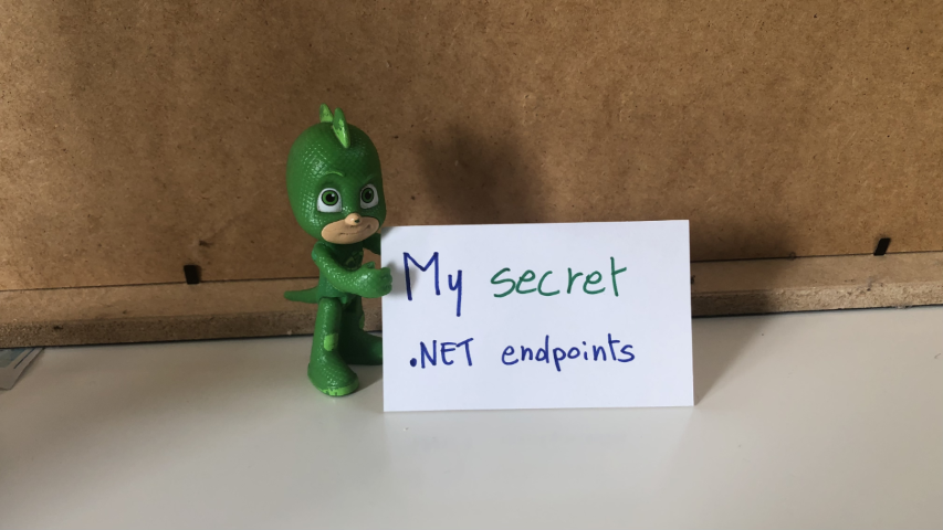
When I create Web APIs with .NET I usually add two “secret” endpoints that I can use to double-check the status of the deployment.
I generally expose two endpoints: one that shows me some info about the current environment, and another one that lists all the application settings defined after the deployment.
In this article, we will see how to create those two endpoints, how to update the values when building the application, and how to hide those endpoints.
Project setup
For this article, I will use a simple .NET 6 API project. We will use Minimal APIs, and we will use the appsettings.json file to load the application’s configuration values.
Since we are using Minimal APIs, you will have the endpoints defined in the Main method within the Program class.
To expose an endpoint that accepts the GET HTTP method, you can write
That’s all you need to know about .NET Minimal APIs for the sake of this article. Let’s move to the main topics ⏩
How to show environment info in .NET APIs
Let’s say that your code execution depends on the current Environment definition. Typical examples are that, if you’re running on production you may want to hide some endpoints otherwise visible in the other environments, or that you will use a different error page when an unhandled exception is thrown.
Once the application has been deployed, how can you retrieve the info about the running environment?
Here we go:
app.MapGet("/env", async context =>
{
    IWebHostEnvironment? hostEnvironment = context.RequestServices.GetRequiredService<IWebHostEnvironment>();
    var thisEnv = new
    {
        ApplicationName = hostEnvironment.ApplicationName,
        Environment = hostEnvironment.EnvironmentName,
    };

    var jsonSerializerOptions = new JsonSerializerOptions { WriteIndented = true };
    await context.Response.WriteAsJsonAsync(thisEnv, jsonSerializerOptions);
});
This endpoint is quite simple.
The context variable, which is of type HttpContext, exposes some properties. Among them, the RequestServices property allows us to retrieve the services that have been injected when starting up the application. We can then use GetRequiredService to get a service by its type and store it into a variable.
💡 GetRequiredService throws an exception if the service cannot be found. On the contrary, GetService returns null. I usually prefer GetRequiredService, but, as always, it depends on what you’re using it.
Then, we create an anonymous object with the information of our interest and finally return them as an indented JSON.
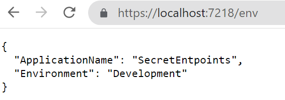
It’s time to run it! Open a terminal, navigate to the API project folder (in my case, SecretEndpoint), and run dotnet run. The application will compile and start; you can then navigate to /env and see the default result:
How to change the Environment value
While the applicationName does not change – it is the name of the running assembly, so any other value will make stop your application from running – you can (and, maybe, want to) change the Environment value.
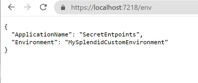
When running the application using the command line, you can use the --environment flag to specify the Environment value.
So, running
dotnet run --environment MySplendidCustomEnvironment
will produce this result:
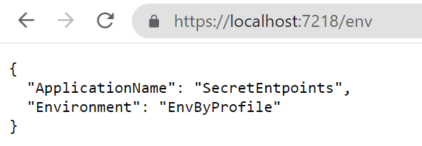
There’s another way to set the environment: update the launchSettings.json and run the application using Visual Studio.
To do that, open the launchSettings.json file and update the profile you are using by specifying the Environment name. In my case, the current profile section will be something like this:
As you can see, the ASPNETCORE_ENVIRONMENT variable is set to EnvByProfile.
If you run the application using Visual Studio using that profile you will see the following result:
How to list all the configurations in .NET APIs
In my current company, we deploy applications using CI/CD pipelines.
This means that final variables definition comes from the sum of 3 sources:
the project’s appsettings file
the release pipeline
the deployment environment
You can easily understand how difficult it is to debug those applications without knowing the exact values for the configurations. That’s why I came up with these endpoints.
To print all the configurations, we’re gonna use an approach similar to the one we’ve used in the previous example.
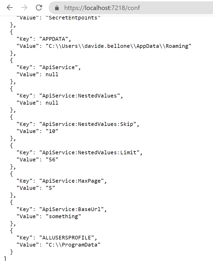
What’s going on? We are retrieving the IConfiguration object, which contains all the configurations loaded at startup; then, we’re listing all the configurations as key-value pairs, and finally, we’re returning the list to the client.
As an example, here’s my current appsettings.json file:
That endpoint shows a lot more than you can imagine: take some time to have a look at those configurations – you’ll thank me later!
How to change the value of a variable
There are many ways to set the value of your variables.
The most common one is by creating an environment-specific appsettings file that overrides some values.
So, if your environment is called “EnvByProfile”, as we’ve defined in the previous example, the file will be named appsettings.EnvByProfile.json.
There are actually some other ways to override application variables: we will learn them in the next article, so stay tuned! 😎
3 ways to hide your endpoints from malicious eyes
Ok then, we have our endpoints up and running, but they are visible to anyone who correctly guesses their addresses. And you don’t want to expose such sensitive info to malicious eyes, right?
There are, at least, 3 simple values to hide those endpoints:
Use a non-guessable endpoint: you can use an existing word, such as “housekeeper”, use random letters, such as “lkfrmlvkpeo”, or use a Guid, such as “E8E9F141-6458-416E-8412-BCC1B43CCB24”;
Specify a key on query string: if that key is not found or it has an invalid value, return a 404-not found result
Use an HTTP header, and, again, return 404 if it is not valid.
Both query strings and HTTP headers are available in the HttpContext object injected in the route definition.
Now it’s your turn to find an appropriate way to hide these endpoints. How would you do that? Drop a comment below 📩
✒ Edit 2022-10-10: I thought it was quite obvious, but apparently it is not: these endpoints expose critical information about your applications and your infrastructure, so you should not expose them unless it is strictly necessary! If you have strong authentication in place, use it to secure those endpoints. If you don’t, hide those endpoints the best you can, and show only necessary data, and not everything. Strip out sensitive content. And, as soon as you don’t need that info anymore, remove those endpoints (comment them out or generate them only if a particular flag is set at compilation time). Another possible way is by using feature flags. In the end, take that example with a grain of salt: learn that you can expose them, but keep in mind that you should not expose them.
Further readings
We’ve used a quite new way to build and develop APIs with .NET, called “Minimal APIs”. You can read more here:
If you are not using Minimal APIs, you still might want to create such endpoints. We’ve talked about accessing the HttpContext to get info about the HTTP headers and query string. When using Controllers, accessing the HttpContext requires some more steps. Here’s an article that you may find interesting:
In a microservices architecture, an API Gateway hides your real endpoints. We will create one using Azure API Management
Table of Contents
Just a second! 🫷 If you are here, it means that you are a software developer.
So, you know that storage, networking, and domain management have a cost .
If you want to support this blog, please ensure that you have disabled the adblocker for this site. I configured Google AdSense to show as few ADS as possible – I don’t want to bother you with lots of ads, but I still need to add some to pay for the resources for my site.
Thank you for your understanding. – Davide
If you’re building an application that exposes several services you might not want to expose them on different hosts. Consumers will have a hard time configuring their application with all the different hostnames, and you will be forced to maintain the same URLs even if you need to move to other platforms or, for instance, you want to transform a REST endpoint into an Azure Function.
In this case, you should mask the real endpoints beneath a facade: maybe… an API Gateway? 🙂
In this article, we will learn how to configure Azure API Management (from now on: APIM) service to create an API Gateway and “hide” our real services.
Demo: publish .NET API services and locate the OpenAPI definition
For the sake of this article, we will work with 2 API services: BooksService and VideosService.
They are both .NET 6 APIs, deployed on Azure using GitHub Actions (using the steps I described in a previous article).
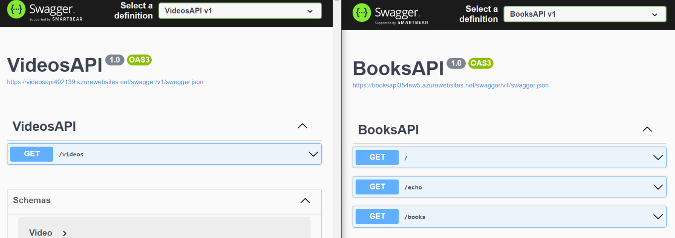
Both services expose their Swagger pages and a bunch of endpoints that we will gonna hide behind Azure APIM.
How to create Azure API Management (APIM) Service from Azure Portal
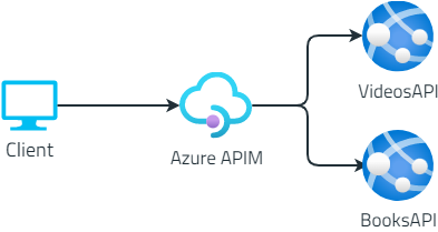
Now, we want to hide their real endpoints. The clients will then only know about the existence of the API Gateway, and not of the two separate API services:
It’s time to create our APIM resource.👷♂️
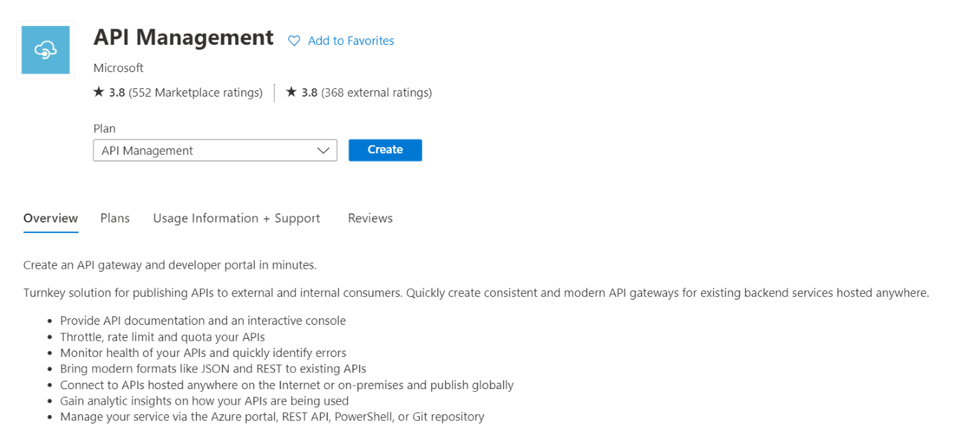
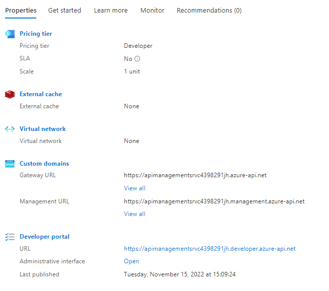
Head to the Azure Portal, and create a new API Management instance. I suggest reading the short overview of the functionalities provided by Azure API Management services as listed in the screenshot below.
The wizard will ask you for some info, such as the resource name, the region, and an email used to send communications (honestly speaking, I still haven’t figured out why they’re asking for your email).
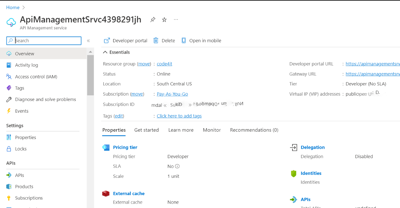
Fill in all the fields, pick your preferred pricing tier (mine is Developer: it doesn’t have an SLA and is quite cheap), and then proceed with the service creation.
After several minutes (it took 50 minutes – fifty!💢 – to scaffold my instance), you will have your instance ready to be used.
We are now ready to add our APIs and expose them to our clients.
How to add APIs to Azure API Management using Swagger definition (OpenAPI)
As we’ve seen in a previous article, Swagger creates a JSON file that describes the operations available in your APIs, as well as the object structures accepted as input and returned as output.
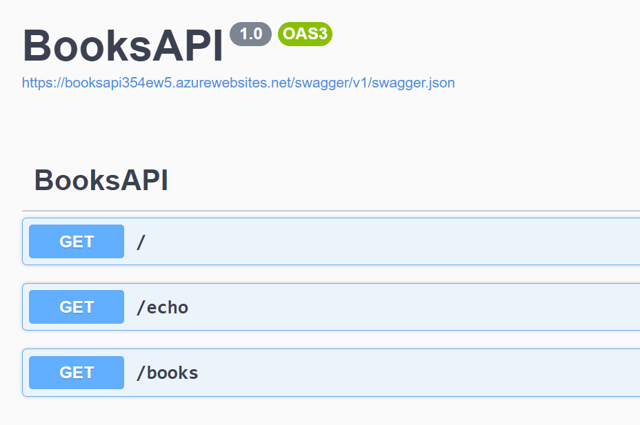
Let me use as an example the Books API: once that API project is deployed on the cloud (it’s not mandatory to use Azure: it will work the same using other cloud vendors), you will see the Swagger UI and the related JSON definition.
We have 3 endpoints, /, /echo, and /books; those endpoints are described in the swagger.json file linked in the Swagger page; put that link aside: we will use it soon.
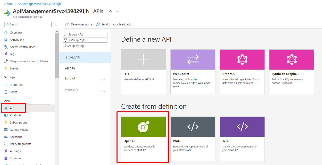
Finally, we can add our Books APIs to our Azure Management API Service! Head to the resource on Azure, locate the APIs menu item on the left panel, and create a new API definition using OpenAPI (which is the standard used by Swagger to create its UI).
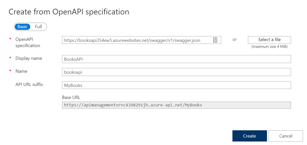
You will see a form that allows you to create new resources from OpenAPI specifications.
Paste here the link to the swagger.json file you located before, populate the required fields and, if you want, add a prefix to identify these endpoints: I choose MyBooks.
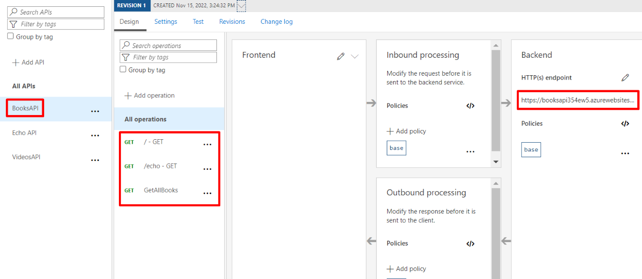
You will then see your APIs appear in the panel shown below. It is composed of different parts:
The list of services exposed. In the screenshot below, BooksAPI, Echo API, and VideosAPI;
The list of endpoints exposed for each service: here, BooksAPI exposes endpoints at /, /echo, and /books;
A list of policies that are applied to the inbound requests before hitting the real endpoint;
The real endpoint used when calling the facade exposed by APIM;
A list of policies applied to the outbound requests after the origin has processed the requests.
For now, we will ignore both Inbound and Outbound processing, as they will be the topic of a future article.
Consuming APIs exposed on the API Gateway
We’re ready to go! Head back to the Azure API Management service dashboard and locate the URL of the API Gateway under Custom domains > Gateway URL.
This will be the root URL that our clients will use.
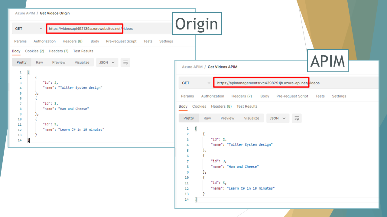
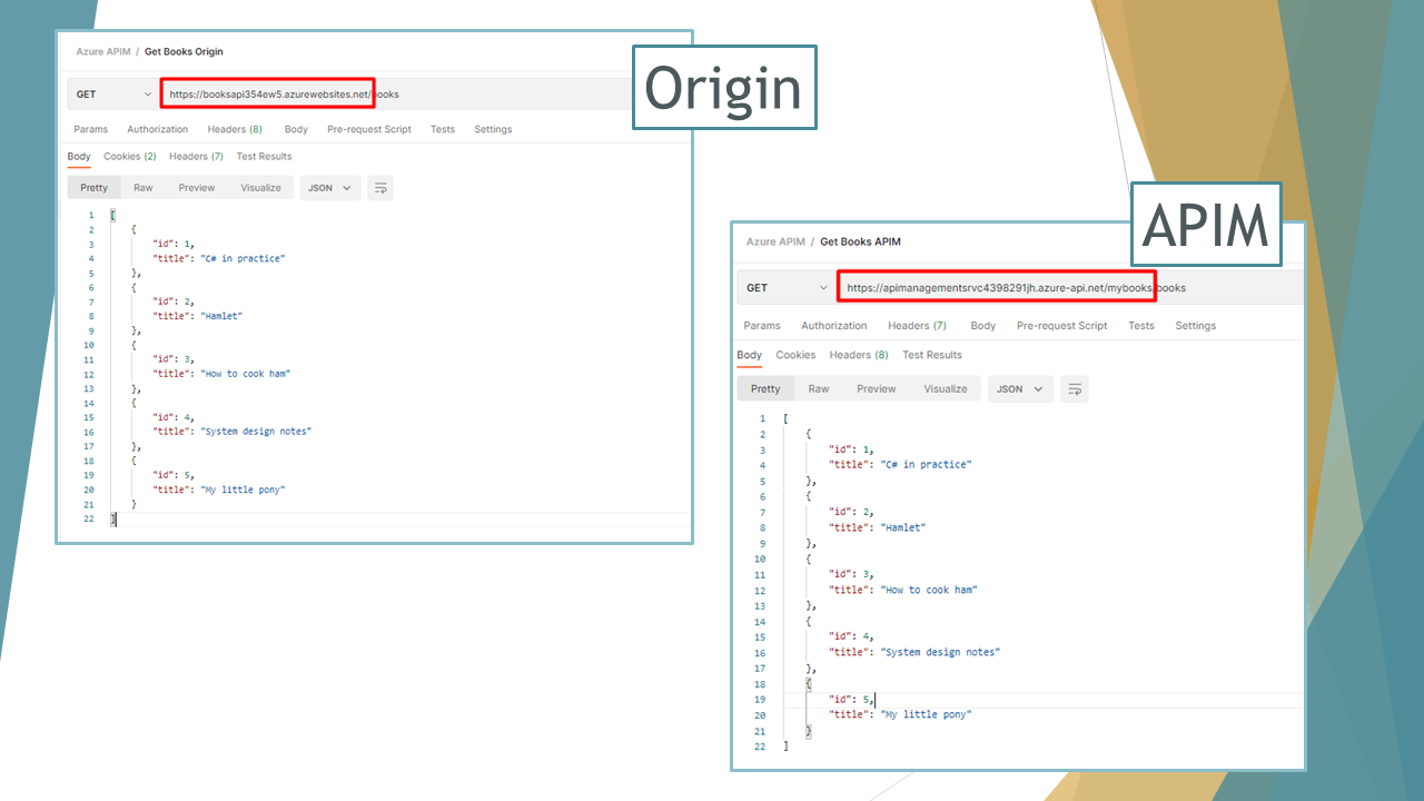
We can then access Books API and Videos API both on the Origin and the Gateway (we’re doing it just for demonstrating that things are working; clients will only use the APIs exposed by the API Gateway).
The Videos API maintains the exact same structure, mapping the endpoints as they are defined in Origin.
On the contrary, to access the Books APIs we have to access the /mybooks path (because we defined it a few steps ago when we imported the BooksAPI from OpenAPI definition: it’s the API Url Suffix field), as shown below:
Further readings
As usual, a bunch of interesting readings 📚
In this article, we’ve only scratched the surface of Azure API Management. There’s way lot – and you can read about it on the Microsoft Docs website:
To integrate Azure APIM, we used two simple dotNET 6 Web APIs deployed on Azure. If you wanna know how to set up GitHub Actions to build and deploy dotNET APIs, I recently published an article on that topic.
This can be just the beginning of a long journey; APIM allows you to highly customize your API Gateway by defining API access by user role, creating API documentation using custom templates and themes, and a lot of different stuff.
Just a second! 🫷 If you are here, it means that you are a software developer.
So, you know that storage, networking, and domain management have a cost .
If you want to support this blog, please ensure that you have disabled the adblocker for this site. I configured Google AdSense to show as few ADS as possible – I don’t want to bother you with lots of ads, but I still need to add some to pay for the resources for my site.
Thank you for your understanding. – Davide
Model validation is fundamental to any project: it brings security and robustness acting as a first shield against an invalid state.
You should then add Unit Tests focused on model validation. In fact, when defining the input model, you should always consider both the valid and, even more, the invalid models, making sure that all the invalid models are rejected.
BDD is a good approach for this scenario, and you can use TDD to implement it gradually.
Okay, but how can you validate that the models and model attributes you defined are correct?
Have we defined our model correctly? Are we covering all the edge cases? A well-written Unit Test suite is our best friend here!
We have two choices: we can write Integration Tests to send requests to our system, which is running an in-memory server, and check the response we receive. Or we can use the internal Validator class, the one used by ASP.NET to validate input models, to create slim and fast Unit Tests. Let’s use the second approach.
Here’s a utility method we can use in our tests:
publicstatic IList<ValidationResult> ValidateModel(object model)
{
var results = new List<ValidationResult>();
var validationContext = new ValidationContext(model, null, null);
Validator.TryValidateObject(model, validationContext, results, true);
if (model is IValidatableObject validatableModel)
results.AddRange(validatableModel.Validate(validationContext));
return results;
}
In short, we create a validation context without any external dependency, focused only on the input model: new ValidationContext(model, null, null).
Next, we validate each field by calling TryValidateObject and store the validation results in a list, result.
Finally, if the Model implements the IValidatableObject interface, which exposes the Validate method, we call that Validate() method and store the returned validation errors in the final result list created before.
As you can see, we can handle both validation coming from attributes on the fields, such as [Required], and custom validation defined in the model class’s Validate() method.
Now, we can use this method to verify whether the validation passes and, in case it fails, which errors are returned:
[Test]publicvoid User_ShouldPassValidation_WhenModelIsValid()
{
var model = new User { FirstName = "Davide", LastName = "Bellone", Age = 32 };
var validationResult = ModelValidationHelper.ValidateModel(mode);
Assert.That(validationResult, Is.Empty);
}
[Test]publicvoid User_ShouldNotPassValidation_WhenLastNameIsEmpty()
{
var model = new User { FirstName = "Davide", LastName = null, Age = 32 };
var validationResult = ModelValidationHelper.ValidateModel(mode);
Assert.That(validationResult, Is.Not.Empty);
}
[Test]publicvoid User_ShouldNotPassValidation_WhenAgeIsLessThan18()
{
var model = new User { FirstName = "Davide", LastName = "Bellone", Age = 10 };
var validationResult = ModelValidationHelper.ValidateModel(mode);
Assert.That(validationResult, Is.Not.Empty);
}
Further readings
Model Validation allows you to create more robust APIs. To improve robustness, you can follow Postel’s law:
Model validation, in my opinion, is one of the cases where Unit Tests are way better than Integration Tests. This is a perfect example of Testing Diamond, the best (in most cases) way to structure a test suite:
If you still prefer writing Integration Tests for this kind of operation, you can rely on the WebApplicationFactory class and use it in your NUnit tests:
For the past few months, I’ve been exploring different kinetic motion designs with text and images. The style looks very intriguing, so I decided to create some really cool organic animations using images and React Three Fiber.
In this article, we’ll learn how to create the following animation using Canvas2D and React Three Fiber.
Setting Up the View & Camera
The camera’s field of view (FOV) plays a huge role in this project. Let’s keep it very low so it looks like an orthographic camera. You can experiment with different perspectives later. I prefer using a perspective camera over an orthographic one because we can always try different FOVs. For more detailed implementation check source code.
4. Add some rotation – Let’s rotate things a bit! First, I’ll hard-code the rotation of our banners to make them more curved and fit nicely with the Billboard component. We’ll also make the radius a bit bigger.
page.jsx
'use client';

import styles from './page.module.scss';
import Billboard from '@/components/webgl/Billboard/Billboard';
import Banner from '@/components/webgl/Banner/Banner';
import { View } from '@/webgl/View';
import { PerspectiveCamera } from '@react-three/drei';

const COUNT = 10;
const GAP = 3.2;

export default function Home() {
    return (
        <div className={styles.page}>
            <View className={styles.view} orbit={false}>
            <PerspectiveCamera makeDefault fov={7} position={[0, 0, 70]} near={0.01} far={100000} />
                <group>
                    {Array.from({ length: COUNT }).map((_, index) => [
                        <Billboard
                        key={`billboard-${index}`}
                        radius={5}
                        position={[0, (index - (Math.ceil(COUNT / 2) - 1)) * GAP, 0]}
                        rotation={[0, index * Math.PI * 0.5, 0]} // <-- rotation of the billboard
                        />,
                        <Banner
                        key={`banner-${index}`}
                        radius={5}
                        rotation={[0, 0, 0.085]} // <-- rotation of the banner
                        position={[0, (index - (Math.ceil(COUNT / 2) - 1)) * GAP - GAP * 0.5, 0]}
                        />,
                    ])}
                </group>
            </View>
        </div>
    );
}
5. Tilt the whole thing – Now let’s rotate our entire group to make it look like the Leaning Tower of Pisa.
page.jsx
'use client';

import styles from './page.module.scss';
import Billboard from '@/components/webgl/Billboard/Billboard';
import Banner from '@/components/webgl/Banner/Banner';
import { View } from '@/webgl/View';
import { PerspectiveCamera } from '@react-three/drei';

const COUNT = 10;
const GAP = 3.2;

export default function Home() {
    return (
        <div className={styles.page}>
            <View className={styles.view} orbit={false}>
            <PerspectiveCamera makeDefault fov={7} position={[0, 0, 70]} near={0.01} far={100000} />
                <group rotation={[-0.15, 0, -0.2]}> // <-- rotate the group
                    {Array.from({ length: COUNT }).map((_, index) => [
                        <Billboard
                        key={`billboard-${index}`}
                        radius={5}
                        position={[0, (index - (Math.ceil(COUNT / 2) - 1)) * GAP, 0]}
                        rotation={[0, index * Math.PI * 0.5, 0]}
                        />,
                        <Banner
                        key={`banner-${index}`}
                        radius={5}
                        rotation={[0, 0, 0.085]}
                        position={[0, (index - (Math.ceil(COUNT / 2) - 1)) * GAP - GAP * 0.5, 0]}
                        />,
                    ])}
                </group>
            </View>
        </div>
    );
}
6. Perfect! – Our 3D shapes are all set up. Now we can add our images to them.
Creating a Texture from Our Images Using Canvas
Here’s the cool part: we’ll put all our images onto a canvas, then use that canvas as a texture on our Billboard shape.
To make this easier, I created some helper functions that simplify the whole process.
getCanvasTexture.js
import * as THREE from 'three';

/**
* Preloads an image and calculates its dimensions
*/
async function preloadImage(imageUrl, axis, canvasHeight, canvasWidth) {
    const img = new Image();

    img.crossOrigin = 'anonymous';

    await new Promise((resolve, reject) => {
        img.onload = () => resolve();
        img.onerror = () => reject(new Error(`Failed to load image: ${imageUrl}`));
        img.src = imageUrl;
    });

    const aspectRatio = img.naturalWidth / img.naturalHeight;

    let calculatedWidth;
    let calculatedHeight;

    if (axis === 'x') {
        // Horizontal layout: scale to fit canvasHeight
        calculatedHeight = canvasHeight;
        calculatedWidth = canvasHeight * aspectRatio;
        } else {
        // Vertical layout: scale to fit canvasWidth
        calculatedWidth = canvasWidth;
        calculatedHeight = canvasWidth / aspectRatio;
    }

    return { img, width: calculatedWidth, height: calculatedHeight };
}

function calculateCanvasDimensions(imageData, axis, gap, canvasHeight, canvasWidth) {
    if (axis === 'x') {
        const totalWidth = imageData.reduce(
        (sum, data, index) => sum + data.width + (index > 0 ? gap : 0), 0);

        return { totalWidth, totalHeight: canvasHeight };
    } else {
        const totalHeight = imageData.reduce(
        (sum, data, index) => sum + data.height + (index > 0 ? gap : 0), 0);

        return { totalWidth: canvasWidth, totalHeight };
    }
}

function setupCanvas(canvasElement, context, dimensions) {
    const { totalWidth, totalHeight } = dimensions;
    const devicePixelRatio = Math.min(window.devicePixelRatio || 1, 2);

    canvasElement.width = totalWidth * devicePixelRatio;
    canvasElement.height = totalHeight * devicePixelRatio;

    if (devicePixelRatio !== 1) context.scale(devicePixelRatio, devicePixelRatio);

    context.fillStyle = '#ffffff';
    context.fillRect(0, 0, totalWidth, totalHeight);
}

function drawImages(context, imageData, axis, gap) {
    let currentX = 0;
    let currentY = 0;

    context.save();

    for (const data of imageData) {
        context.drawImage(data.img, currentX, currentY, data.width, data.height);

        if (axis === 'x') currentX += data.width + gap;
        else currentY += data.height + gap;
    }

    context.restore();
}

function createTextureResult(canvasElement, dimensions) {
    const texture = new THREE.CanvasTexture(canvasElement);
    texture.needsUpdate = true;
    texture.wrapS = THREE.RepeatWrapping;
    texture.wrapT = THREE.ClampToEdgeWrapping;
    texture.generateMipmaps = false;
    texture.minFilter = THREE.LinearFilter;
    texture.magFilter = THREE.LinearFilter;

    return {
        texture,
        dimensions: {
            width: dimensions.totalWidth,
            height: dimensions.totalHeight,
            aspectRatio: dimensions.totalWidth / dimensions.totalHeight,
        },
    };
}

export async function getCanvasTexture({
    images,
    gap = 10,
    canvasHeight = 512,
    canvasWidth = 512,
    canvas,
    ctx,
    axis = 'x',
}) {
    if (!images.length) throw new Error('No images');

    // Create canvas and context if not provided
    const canvasElement = canvas || document.createElement('canvas');
    const context = ctx || canvasElement.getContext('2d');

    if (!context) throw new Error('No context');

    // Preload all images in parallel
    const imageData = await Promise.all(
        images.map((image) => preloadImage(image.url, axis, canvasHeight, canvasWidth))
    );

    // Calculate total canvas dimensions
    const dimensions = calculateCanvasDimensions(imageData, axis, gap, canvasHeight, canvasWidth);

    // Setup canvas
    setupCanvas(canvasElement, context, dimensions);

    // Draw all images
    drawImages(context, imageData, axis, gap);

    // Create and return texture result
    return createTextureResult(canvasElement, dimensions)
}
Then we can also create a useCollageTexture hook that we can easily use in our components.
Now let’s use our useCollageTexture hook on our page. We’ll create some simple loading logic. It takes a second to fetch all the images and put them onto the canvas. Then we’ll pass our texture and dimensions of canvas into the Billboard component.
page.jsx
'use client';

import styles from './page.module.scss';
import Billboard from '@/components/webgl/Billboard/Billboard';
import Banner from '@/components/webgl/Banner/Banner';
import Loader from '@/components/ui/modules/Loader/Loader';
import images from '@/data/images';
import { View } from '@/webgl/View';
import { PerspectiveCamera } from '@react-three/drei';
import { useCollageTexture } from '@/hooks/useCollageTexture';

const COUNT = 10;
const GAP = 3.2;

export default function Home() {
    const { texture, dimensions, isLoading } = useCollageTexture(images); // <-- getting the texture and dimensions from the useCollageTexture hook

    if (isLoading) return <Loader />; // <-- showing the loader when the texture is loading

    return (
        <div className={styles.page}>
            <View className={styles.view} orbit={false}>
                <PerspectiveCamera makeDefault fov={7} position={[0, 0, 100]} near={0.01} far={100000} />
                <group rotation={[-0.15, 0, -0.2]}>
                    {Array.from({ length: COUNT }).map((_, index) => [
                        <Billboard
                            key={`billboard-${index}`}
                            radius={5}
                            rotation={[0, index * Math.PI * 0.5, 0]}
                            position={[0, (index - (Math.ceil(COUNT / 2) - 1)) * GAP, 0]}
                            texture={texture} // <--passing the texture to the billboard
                            dimensions={dimensions} // <--passing the dimensions to the billboard
                        />,
                        <Banner
                            key={`banner-${index}`}
                            radius={5.035}
                            rotation={[0, 0, 0.085]}
                            position={[
                                0,
                                (index - (Math.ceil(COUNT / 2) - 1)) * GAP - GAP * 0.5,
                                0,
                            ]}
                        />,
                    ])}
                </group>
            </View>
        </div>
    );
}
Inside the Billboard component, we need to properly map this texture to make sure everything fits correctly. The width of our canvas will match the circumference of the cylinder, and we’ll center the y position of the texture. This way, all the images keep their resolution and don’t get squished or stretched.
Now let’s animate them using the useFrame hook. The trick to animating these images is to just move the X offset of the texture. This gives us the effect of a rotating mesh, when really we’re just moving the texture offset.
I think it would look even better if we made the back of the images a little darker. To do this, I created MeshImageMaterial – it’s just an extension of MeshBasicMaterial that makes our backface a bit darker.
MeshImageMaterial.js
import * as THREE from 'three';
import { extend } from '@react-three/fiber';

export class MeshImageMaterial extends THREE.MeshBasicMaterial {
    constructor(parameters = {}) {
        super(parameters);
        this.setValues(parameters);
    }

    onBeforeCompile = (shader) => {
        shader.fragmentShader = shader.fragmentShader.replace(
            '#include <color_fragment>',
            /* glsl */ `#include <color_fragment>
            if (!gl_FrontFacing) {
            vec3 blackCol = vec3(0.0);
            diffuseColor.rgb = mix(diffuseColor.rgb, blackCol, 0.7);
            }
            `
        );
    };
}

extend({ MeshImageMaterial });
And now we have our images moving around cylinders. Next, we’ll focus on banners (or marquees, whatever you prefer).
Adding Texture to the Banner
The last thing we need to fix is our Banner component. I wrapped it with this texture. Feel free to take it and edit it however you want, but remember to keep the proper dimensions of the texture.
We simply import our texture using the useTexture hook, map it onto our material, and animate the texture offset just like we did in our Billboard component.
Billboard.jsx
'use client';

import * as THREE from 'three';
import bannerTexture from '@/assets/images/banner.jpg';
import { useTexture } from '@react-three/drei';
import { useFrame } from '@react-three/fiber';
import { useRef } from 'react';

function Banner({ radius = 1.6, ...props }) {
    const ref = useRef(null);

    const texture = useTexture(bannerTexture.src);
    texture.wrapS = texture.wrapT = THREE.RepeatWrapping;

    useFrame((state, delta) => {
        if (!ref.current) return;
        const material = ref.current.material;
        if (material.map) material.map.offset.x += delta / 30;
    });

    return (
        <mesh ref={ref} {...props}>
            <cylinderGeometry
                args={[radius, radius, radius * 0.07, radius * 80, radius * 10, true]}
            />
            <meshBasicMaterial
                map={texture}
                map-anisotropy={16}
                map-repeat={[15, 1]}
                side={THREE.DoubleSide}
                toneMapped={false}
                backfaceRepeatX={3}
            />
        </mesh>
    );
}

export default Banner;
Nice! Now we have something cool, but I think it would look even cooler if we replaced the backface with something different. Maybe a gradient? For this, I created another extension of MeshBasicMaterial called MeshBannerMaterial. As you probably guessed, we just put a gradient on the backface. That’s it! Let’s use it in our Banner component.
We replace the MeshBasicMaterial with MeshBannerMaterial and now it looks like this!
MeshBannerMaterial.js
import * as THREE from 'three';
import { extend } from '@react-three/fiber';

export class MeshBannerMaterial extends THREE.MeshBasicMaterial {
    constructor(parameters = {}) {
        super(parameters);
        this.setValues(parameters);

        this.backfaceRepeatX = 1.0;

        if (parameters.backfaceRepeatX !== undefined)

        this.backfaceRepeatX = parameters.backfaceRepeatX;
    }

    onBeforeCompile = (shader) => {
        shader.uniforms.repeatX = { value: this.backfaceRepeatX * 0.1 };
        shader.fragmentShader = shader.fragmentShader
        .replace(
            '#include <common>',
            /* glsl */ `#include <common>
            uniform float repeatX;

            vec3 pal( in float t, in vec3 a, in vec3 b, in vec3 c, in vec3 d ) {
                return a + b*cos( 6.28318*(c*t+d) );
            }
            `
        )
        .replace(
            '#include <color_fragment>',
            /* glsl */ `#include <color_fragment>
            if (!gl_FrontFacing) {
            diffuseColor.rgb = pal(vMapUv.x * repeatX, vec3(0.5,0.5,0.5),vec3(0.5,0.5,0.5),vec3(1.0,1.0,1.0),vec3(0.0,0.10,0.20) );
            }
            `
        );
    };
}

extend({ MeshBannerMaterial });
Banner.jsx
'use client';

import * as THREE from 'three';
import bannerTexture from '@/assets/images/banner.jpg';
import { useTexture } from '@react-three/drei';
import { useFrame } from '@react-three/fiber';
import { useRef } from 'react';
import '@/webgl/materials/MeshBannerMaterial';

function Banner({ radius = 1.6, ...props }) {
const ref = useRef(null);

const texture = useTexture(bannerTexture.src);

texture.wrapS = texture.wrapT = THREE.RepeatWrapping;

useFrame((state, delta) => {
    if (!ref.current) return;

    const material = ref.current.material;

    if (material.map) material.map.offset.x += delta / 30;
});

return (
    <mesh ref={ref} {...props}>
        <cylinderGeometry
            args={[radius, radius, radius * 0.07, radius * 80, radius * 10, true]}
        />
        <meshBannerMaterial
            map={texture}
            map-anisotropy={16}
            map-repeat={[15, 1]}
            side={THREE.DoubleSide}
            toneMapped={false}
            backfaceRepeatX={3}
        />
    </mesh>
);
}

export default Banner;
You can experiment with this method in lots of ways. For example, I created 2 more examples with shapes I made in Blender, and mapped canvas textures on them. You can check them out here:
Final Words
Check out the final versions of all demos:
I hope you enjoyed this tutorial and learned something new!
Feel free to check out the source code for more details!
Learn how to zip and unzip compressed files with C#. Beware: it’s not as obvious as it might seem!
Table of Contents
Just a second! 🫷 If you are here, it means that you are a software developer.
So, you know that storage, networking, and domain management have a cost .
If you want to support this blog, please ensure that you have disabled the adblocker for this site. I configured Google AdSense to show as few ADS as possible – I don’t want to bother you with lots of ads, but I still need to add some to pay for the resources for my site.
Thank you for your understanding. – Davide
When working with local files, you might need to open, create, or update Zip files.
In this article, we will learn how to work with Zip files in C#. We will learn how to perform basic operations such as opening, extracting, and creating a Zip file.
The main class we will use is named ZipFile, and comes from the System.IO.Compression namespace. It’s been present in C# since .NET Framework 4.5, so we can say it’s pretty stable 😉 Nevertheless, there are some tricky points that you need to know before using this class. Let’s learn!
Using C# to list all items in a Zip file
Once you have a Zip file, you can access the internal items without extracting the whole Zip.
You can use the ZipFile.Open method.
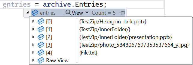
using ZipArchive archive = ZipFile.Open(zipFilePath, ZipArchiveMode.Read);
System.Collections.ObjectModel.ReadOnlyCollection<ZipArchiveEntry> entries = archive.Entries;
Notice that I specified the ZipArchiveMode. This is an Enum whose values are Read, Create, and Update.
Using the Entries property of the ZipArchive, you can access the whole list of files stored within the Zip folder, each represented by a ZipArchiveEntry instance.
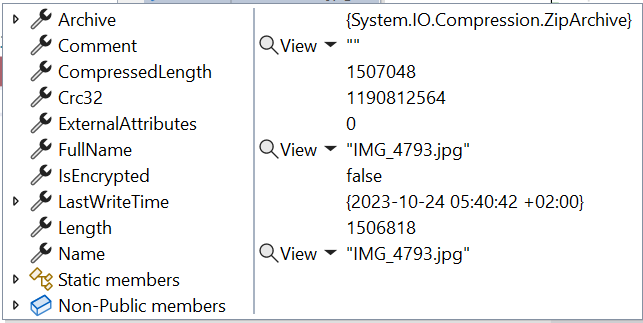
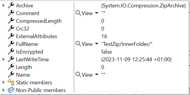
The ZipArchiveEntry object contains several fields, like the file’s name and the full path from the root archive.
There are a few key points to remember about the entries listed in the ZipArchiveEntry.
It is a ReadOnlyCollection<ZipArchiveEntry>: it means that even if you find a way to add or update the items in memory, the changes are not applied to the actual files;
It lists all files and folders, not only those at the root level. As you can see from the image above, it lists both the files at the root level, like File.txt, and those in inner folders, such as TestZip/InnerFolder/presentation.pptx;
Each file is characterized by two similar but different properties: Name is the actual file name (like presentation.pptx), while FullName contains the path from the root of the archive (e.g. TestZip/InnerFolder/presentation.pptx);
It lists folders as if they were files: in the image above, you can see TestZip/InnerFolder. You can recognize them because their Name property is empty and their Length is 0;
Lastly, remember that ZipFile.Open returns an IDisposable, so you should place the operations within a using statement.
❓❓A question for you! Why do we see an item for the TestZip/InnerFolder folder, but there is no reference to the TestZip folder? Drop a comment below 📩
Extracting a Zip folder is easy but not obvious.
We have only one way to do that: by calling the ZipFile.ExtractToDirectory method.
It accepts as mandatory parameters the path of the Zip file to be extracted and the path to the destination:
var zipPath = @"C:\Users\d.bellone\Desktop\TestZip.zip";
var destinationPath = @"C:\Users\d.bellone\Desktop\MyDestination";
ZipFile.ExtractToDirectory(zipPath, destinationPath);
Once you run it, you will see the content of the Zip copied and extracted to the MyDestination folder.
Note that this method creates the destination folder if it does not exist.
This method accepts two more parameters:
entryNameEncoding, by which you can specify the encoding. The default value is UTF-8.
overwriteFiles allows you to specify whether it must overwrite existing files. The default value is false. If set to false and the destination files already exist, this method throws a System.IO.IOException saying that the file already exists.
Using C# to create a Zip from a folder
The key method here is ZipFile.CreateFromDirectory, which allows you to create Zip files in a flexible way.
The first mandatory value is, of course, the source directory path.
The second mandatory parameter is the destination of the resulting Zip file.
Or it can be a Stream that you can use later for other operations:
using (MemoryStream memStream = new MemoryStream())
{
string sourceFolderPath = @"\Desktop\myFolder";
ZipFile.CreateFromDirectory(sourceFolderPath, memStream);
var lenght = memStream.Length;// here the Stream is populated}
You can finally add some optional parameters:
compressionLevel, whose values are Optimal, Fastest, NoCompression, SmallestSize.
includeBaseDirectory: a flag that defines if you have to copy only the first-level files or also the root folder.
A quick comparison of the four Compression Levels
As we just saw, we have four compression levels: Optimal, Fastest, NoCompression, and SmallestSize.
What happens if I use the different values to zip all the photos and videos of my latest trip?
Fastest compression generates a smaller file than Smallest compression.
Fastest compression is way slower than Smallest compression.
Optimal lies in the middle.
This is to say: don’t trust the names; remember to benchmark the parts where you need performance, even with a test as simple as this.
Wrapping up
This was a quick article about one specific class in the .NET ecosystem.
As we saw, even though the class is simple and it’s all about three methods, there are some things you should keep in mind before using this class in your code.
I hope you enjoyed this article! Let’s keep in touch on Twitter or LinkedIn! 🤜🤛
C# devs have the bad habit of creating interfaces for every non-DTO class because «we need them for mocking!». Are you sure it’s the only way?
Table of Contents
Just a second! 🫷 If you are here, it means that you are a software developer.
So, you know that storage, networking, and domain management have a cost .
If you want to support this blog, please ensure that you have disabled the adblocker for this site. I configured Google AdSense to show as few ADS as possible – I don’t want to bother you with lots of ads, but I still need to add some to pay for the resources for my site.
Thank you for your understanding. – Davide
One of the most common traits of C# developers is the excessive usage of interfaces.
For every non-DTO class we define, we usually also create the related interface. Most of the time, we don’t need it because we have multiple implementations of an interface. Instead, we say that we need an interface to enable mocking.
That’s true; it’s pretty straightforward to mock an interface: lots of libraries, like Moq and NSubstitute, allow you to create mocks and pass them to the class under test. What if there were another way?
In this article, we will learn how to have complete control over a dependency while having the concrete class, and not the related interface, injected in the constructor.
C# devs always add interfaces, just in case
If you’re a developer like me, you’ve been taught something like this:
One of the SOLID principles is Dependency Inversion; to achieve it, you need Dependency Injection. The best way to do that is by creating an interface, injecting it in the consumer’s constructor, and then mapping the interface and the concrete class.
Sometimes, somebody explains that we don’t need interfaces to achieve Dependency Injection. However, there are generally two arguments proposed by those who keep using interfaces everywhere: the “in case I need to change the database” argument and, even more often, the “without interfaces, I cannot create mocks”.
Are we sure?
The “Just in case I need to change the database” argument
One phrase that I often hear is:
Injecting interfaces allows me to change the concrete implementation of a class without worrying about the caller. You know, just in case I had to change the database engine…
Yes, that’s totally right – using interfaces, you can change the internal implementation in a bat of an eye.
Let’s be honest: in all your career, how many times have you changed the underlying database? In my whole career, it happened just once: we tried to build a solution using Gremlin for CosmosDB, but it turned out to be too expensive – so we switched to a simpler MongoDB.
But, all in all, it wasn’t only thanks to the interfaces that we managed to switch easily; it was because we strictly separated the classes and did not leak the models related to Gremlin into the core code. We structured the code with a sort of Hexagonal Architecture, way before this term became a trend in the tech community.
Still, interfaces can be helpful, especially when dealing with multiple implementations of the same methods or when you want to wrap your head around the methods, inputs, and outputs exposed by a module.
The “I need to mock” argument
Another one I like is this:
Interfaces are necessary for mocking dependencies! Otherwise, how can I create Unit Tests?
Well, I used to agree with this argument. I was used to mocking interfaces by using libraries like Moq and defining the behaviour of the dependency using the SetUp method.
It’s still a valid way, but my point here is that that’s not the only one!
One of the simplest tricks is to mark your classes as abstract. But… this means you’ll end up with every single class marked as abstract. Not the best idea.
We have other tools in our belt!
A realistic example: Dependency Injection without interfaces
Let’s start with a real-ish example.
We have a NumbersRepository that just exposes one method: GetNumbers().
publicclassNumbersRepository{
privatereadonlyint[] _allNumbers;
public NumbersRepository()
{
_allNumbers = Enumerable.Range(0, int.MaxValue).ToArray();
}
public IEnumerable<int> GetNumbers() => Random.Shared.GetItems(_allNumbers, 50);
}
Generally, one would be tempted to add an interface with the same name as the class, INumbersRepository, and include the GetNumbers method in the interface definition.
We are not going to do that – the interface is not necessary, so why clutter the code with something like that?
Now, for the consumer. We have a simple NumbersSearchService that accepts, via Dependency Injection, an instance of NumbersRepository (yes, the concrete class!) and uses it to perform a simple search:
We have overridden the GetNumbers method, but to do so, we had to include a new method, SetNumbers, to define the expected result of the former method.
We then can use it in our tests like this:
[Test]publicvoid Should_WorkWithStubRepo()
{
// Arrangevar repository = new StubNumberRepo();
repository.SetNumbers(1, 2, 3);
var service = new NumbersSearchService(repository);
// Actvar result = service.Contains(3);
// Assert Assert.That(result, Is.True);
}
You now have the full control over the subclass. But this approach comes with a problem: if you have multiple methods marked as virtual, and you are going to use all of them in your test classes, then you will need to override every single method (to have control over them) and work out how to decide whether to use the concrete method or the stub implementation.
For example, we can update the StubNumberRepo to let the consumer choose if we need the dummy values or the base implementation:
With this approach, by default, we use the concrete implementation of NumbersRepository because _useStubNumbers is false. If we call the SetNumbers method, we also specify that we don’t want to use the original implementation.
Way 2: Use the virtual keyword in the service to avoid calling the dependency
Similar to the previous approach, we can mark some methods of the caller as virtual to allow us to change parts of our class while keeping everything else as it was.
To achieve it, we have to refactor a little our Service class:
public class NumbersSearchService
{
private readonly NumbersRepository _repository;
public NumbersSearchService(NumbersRepository repository)
{
_repository = repository;
}
public bool Contains(int number)
{
- var numbers = _repository.GetNumbers();
+ var numbers = GetNumbers();
return numbers.Contains(number);
}
+ public virtual IEnumerable<int> GetNumbers() => _repository.GetNumbers();
}
The key is that we moved the calls to the external references to a separate method, marking it as virtual.
This way, we can create a stub class of the Service itself without the need to stub its dependencies:
The approach is almost identical to the one we saw before. The difference can be seen in your tests:
[Test]publicvoid Should_UseStubService()
{
// Arrangevar service = new StubNumberSearch();
service.SetNumbers(12, 15, 30);
// Actvar result = service.Contains(15);
// Assert Assert.That(result, Is.True);
}
There is a problem with this approach: many devs (correctly) add null checks in the constructor to ensure that the dependencies are not null:
public NumbersSearchService(NumbersRepository repository)
{
ArgumentNullException.ThrowIfNull(repository);
_repository = repository;
}
While this approach makes it safe to use the NumbersSearchService reference within the class’ methods, it also stops us from creating a StubNumberSearch. Since we want to create an instance of NumbersSearchService without the burden of injecting all the dependencies, we call the base constructor passing null as a value for the dependencies. If we validate against null, the stub class becomes unusable.
There’s a simple solution: adding a protected empty constructor:
We mark it as protected because we want that only subclasses can access it.
Way 3: Use the “new” keyword in methods to hide the base implementation
Similar to the virtual keyword is the new keyword, which can be applied to methods.
We can then remove the virtual keyword from the base class and hide its implementation by marking the overriding method as new.
public class NumbersSearchService
{
private readonly NumbersRepository _repository;
public NumbersSearchService(NumbersRepository repository)
{
ArgumentNullException.ThrowIfNull(repository);
_repository = repository;
}
public bool Contains(int number)
{
var numbers = _repository.GetNumbers();
return numbers.Contains(number);
}
- public virtual IEnumerable<int> GetNumbers() => _repository.GetNumbers();
+ public IEnumerable<int> GetNumbers() => _repository.GetNumbers();
}
We have restored the original implementation of the Repository.
Now, we can update the stub by adding the new keyword.
internal class StubNumberSearch : NumbersSearchService
{
private IEnumerable<int> _numbers;
private bool _useStubNumbers;
public void SetNumbers(params int[] numbers)
{
_numbers = numbers.ToArray();
_useStubNumbers = true;
}
- public override IEnumerable<int> GetNumbers() => _useStubNumbers ? _numbers : base.GetNumbers();
+ public new IEnumerable<int> GetNumbers() => _useStubNumbers ? _numbers : base.GetNumbers();
}
We haven’t actually solved any problem except for one: we can now avoid cluttering all our classes with the virtual keyword.
A question for you! Is there any difference between using the new and the virtual keyword? When you should pick one instead of the other? Let me know in the comments section! 📩
Way 4: Mock concrete classes by marking a method as virtual
Sometimes, I hear developers say that mocks are the absolute evil, and you should never use them.
Oh, come on! Don’t be so silly!
That’s true, when using mocks you are writing tests on a irrealistic environment. But, well, that’s exactly the point of having mocks!
If you think about it, at school, during Science lessons, we were taught to do our scientific calculations using approximations: ignore the air resistance, ignore friction, and so on. We knew that that world did not exist, but we removed some parts to make it easier to validate our hypothesis.
In my opinion, it’s the same for testing. Mocks are useful to have full control of a specific behaviour. Still, only relying on mocks makes your tests pretty brittle: you cannot be sure that your system is working under real conditions.
That’s why, as I explained in a previous article, I prefer the Testing Diamond over the Testing Pyramid. In many real cases, five Integration Tests are more valuable than fifty Unit Tests.
But still, mocks can be useful. How can we use them if we don’t have interfaces?
If we try to use Moq to create a mock of NumbersRepository (again, the concrete class) like this:
[Test]publicvoid Should_WorkWithMockRepo()
{
// Arrangevar repository = new Moq.Mock<NumbersRepository>();
repository.Setup(_ => _.GetNumbers()).Returns(newint[] { 1, 2, 3 });
var service = new NumbersSearchService(repository.Object);
// Actvar result = service.Contains(3);
// Assert Assert.That(result, Is.True);
}
It will fail with this error:
System.NotSupportedException : Unsupported expression: _ => _.GetNumbers()
Non-overridable members (here: NumbersRepository.GetNumbers) may not be used in setup / verification expressions.
This error occurs because the implementation GetNumbers is fixed as defined in the NumbersRepository class and cannot be overridden.
Unless you mark it as virtual, as we did before.
public class NumbersRepository
{
    private readonly int[] _allNumbers;

    public NumbersRepository()
    {
        _allNumbers = Enumerable.Range(0, 100).ToArray();
    }

-    public IEnumerable<int> GetNumbers() => Random.Shared.GetItems(_allNumbers, 50);
+    public virtual IEnumerable<int> GetNumbers() => Random.Shared.GetItems(_allNumbers, 50);
}
Now the test passes: we have successfully mocked a concrete class!
Further readings
Testing is a crucial part of any software application. I personally write Unit Tests even for throwaway software – this way, I can ensure that I’m doing the correct thing without the need for manual debugging.
However, one part that is often underestimated is the code quality of tests. Tests should be written even better than production code. You can find more about this topic here:
Also, Unit Tests are not enough. You should probably write more Integration Tests than Unit Tests. This one is a testing strategy called Testing Diamond.
In this article, we learned that it’s not necessary to create interfaces for the sake of having mocks.
We have different other options.
Honestly speaking, I’m still used to creating interfaces and using them with mocks.
I find it easy to do, and this approach provides a quick way to create tests and drive the behaviour of the dependencies.
Also, I recognize that interfaces created for the sole purpose of mocking are quite pointless: we have learned that there are other ways, and we should consider trying out these solutions.
Still, interfaces are quite handy for two “non-technical” reasons:
using interfaces, you can understand in a glimpse what are the operations that you can call in a clean and concise way;
interfaces and mocks allow you to easily use TDD: while writing the test cases, you also define what methods you need and the expected behaviour. I know you can do that using stubs, but I find it easier with interfaces.
I know, this is a controversial topic – I’m not saying that you should remove all your interfaces (I think it’s a matter of personal taste, somehow!), but with this article, I want to highlight that you can avoid interfaces.
I hope you enjoyed this article! Let’s keep in touch on Twitter or LinkedIn! 🤜🤛
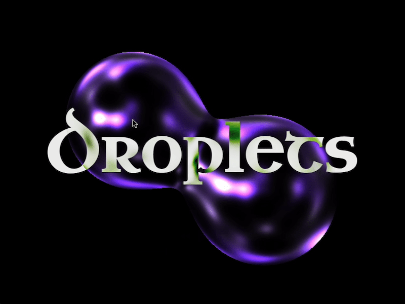
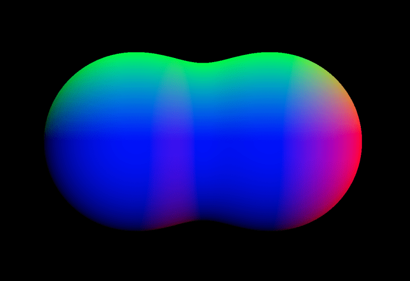
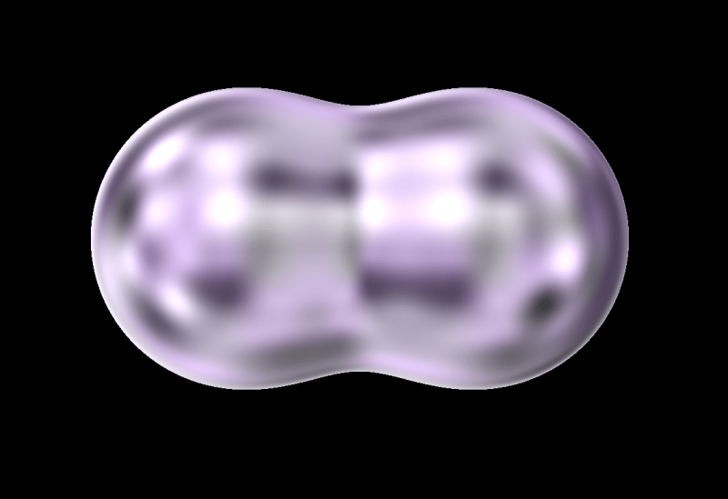
Fragment shaders allow us to create smooth, organic visuals that are difficult to achieve with standard polygon-based rendering in WebGL. One powerful example is the metaball effect, where multiple objects blend and deform seamlessly. This can be implemented using a technique called ray marching, directly within a fragment shader.
In this tutorial, we’ll walk you through how to create droplet-like, bubble spheres using Three.js and GLSL—an effect that responds interactively to your mouse movements. But first, take a look at the demo video below to see the final result in action.
Overview
Let’s take a look at the overall structure of the demo and review the steps we’ll follow to build it.
We arrange spheres along the mouse trail to create a stretchy, elastic motion.
Let’s get started!
1. Setup
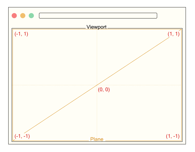
We render a single fullscreen plane that covers the entire viewport.
// Output.ts

const planeGeometry = new THREE.PlaneGeometry(2.0, 2.0);
const planeMaterial = new THREE.RawShaderMaterial({
    vertexShader: base_vert,
    fragmentShader: output_frag,
    uniforms: this.uniforms,
});
const plane = new THREE.Mesh(planeGeometry, planeMaterial);
this.scene.add(plane);
We define a uniform variable named uResolution to pass the canvas size to the shader, where Common.width and Common.height represent the width and height of the canvas in pixels. This uniform will be used to normalize coordinates based on the screen resolution.
The vertex shader receives the position attribute.
Since the xy components of position originally range from -1 to 1, we convert them to a range from 0 to 1 and output them as a texture coordinate called vTexCoord. This is passed to the fragment shader and used to calculate colors or effects based on the position on the screen.
The fragment shader receives the interpolated texture coordinate vTexCoord and the uniform variable uResolution representing the canvas size. Here, we temporarily use vTexCoord to output color for testing.
Now we’re all set to start drawing in the fragment shader! Next, let’s move on to actually rendering the spheres.
2. Ray Marching
2.1. What is Ray Marching?
As mentioned at the beginning, we will use a method called ray marching to render spheres. Ray marching proceeds in the following steps:
Define the scene
Set the camera (viewing) direction
Cast rays
Evaluate the distance from the current ray position to the nearest object in the scene.
Move the ray forward by that distance
Check for a hit
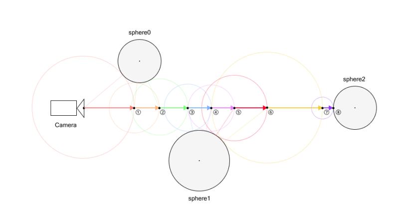
For example, let’s consider a scene with three spheres. These spheres are expressed using SDFs (Signed Distance Functions), which will be explained in detail later.
First, we determine the camera direction. Once the direction is set, we cast a ray in that direction.
Next, we evaluate the distance to all objects from the current ray position, and take the minimum of these distances.
After obtaining this distance, we move the ray forward by that amount.
We repeat this process until either the ray gets close enough to an object—closer than a small threshold—or the maximum number of steps is reached. If the distance is below the threshold, we consider it a “hit” and shade the corresponding pixel.
For example, in the figure above, a hit is detected on the 8th ray marching step.
If the maximum number of steps were set to 7, the 7th step would not have hit anything yet. But since the limit is reached, the loop ends and no hit is detected.
Therefore, nothing would be rendered at that position. If parts of an object appear to be missing in the final image, it may be due to an insufficient number of steps. However, be aware that increasing the step count will also increase the computational load.
To better understand this process, try running this demo to see how it works in practice.
2.2. Signed Distance Function
In the previous section, we briefly mentioned the SDF (Signed Distance Function). Let’s take a moment to understand what it is.
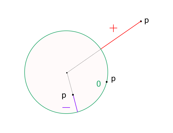
An SDF is a function that returns the distance from a point to a particular shape. The key characteristic is that it returns a positive or negative value depending on whether the point is outside or inside the shape.
For example, here is the distance function for a sphere:
Here, p is a vector representing the position relative to the origin, and s is the radius of the sphere.
This function calculates how far the point p is from the surface of a sphere centered at the origin with radius s.
If the result is positive, the point is outside the sphere.
If negative, it is inside the sphere.
If the result is zero, the point is on the surface—this is considered a hit point (in practice, we detect a hit when the distance is less than a small threshold).
In this demo, we use a sphere’s distance function, but many other shapes have their own distance functions as well.
After that, inside the map function, two spheres are defined and their distances calculated using sdSphere. The variable d is initially set to a large value and updated with the min function to keep track of the shortest distance to the surface.
Then we run a ray marching loop, which updates the ray position by computing the distance to the nearest object at each step. The loop ends either after a fixed number of iterations or when the distance becomes smaller than a threshold (dist < EPS):
for ( int i = 0; i < ITR; ++ i ) {
	dist = map(ray);
	ray += rayDirection * dist;
	if ( dist < EPS ) break ;
}
Finally, we determine the output color. We use black as the default color (background), and render a white pixel only if a hit is detected:
vec3 color = vec3(0.0);

if ( dist < EPS ) {
	color = vec3(1.0);
}
We’ve successfully rendered two overlapping spheres using ray marching!
2.4. Normals
Although we successfully rendered spheres in the previous section, the scene still looks flat and lacks depth. This is because we haven’t applied any shading or visual effects that respond to surface orientation.
While we won’t implement full shading in this demo, we’ll still compute surface normals, as they’re essential for adding surface detail and other visual effects.
At first glance, this may seem hard to understand. Put simply, this computes the gradient of the distance function, which corresponds to the normal vector.
If you’ve studied vector calculus, this might be easy to understand. For many others, though, it may seem a bit difficult.
However, for those who are interested in how it works, we’ll now walk through the explanation in more detail.
The gradient of a scalar function 𝑓(𝑥,𝑦,𝑧) is simply a vector composed of its partial derivatives. It points in the direction of the greatest rate of increase of the function:
To compute this gradient numerically, we can use the central difference method. For example:
We apply the same idea for the 𝑦 and 𝑧 components. Note: The factor 2𝜀 is omitted in the code since we normalize the result using normalize().
Next, let us consider a signed distance function 𝑓(𝑥,𝑦,𝑧), which returns the shortest distance from any point in space to the surface of an object. By definition, 𝑓(𝑥,𝑦,𝑧)=0 on the surface of the object.
Assume that 𝑓 is smooth (i.e., differentiable) in the region of interest. When the point (𝑥,𝑦,𝑧) undergoes a small displacement Δ𝒓=(Δ𝑥,Δ𝑦,Δ𝑧), the change in the function value Δ𝑓 can be approximated using the first-order Taylor expansion:
Here,∇𝑓 is the gradient vector of 𝑓, and Δ𝒓 is an arbitrary small displacement vector.
Now, since 𝑓=0 on the surface and remains constant as we move along the surface (i.e., tangentially), the function value does not change, so Δ𝑓=0. Therefore:
This means that the gradient vector is perpendicular to any tangent vector Δ𝒓 on the surface. In other words, the gradient vector ∇𝑓 points in the direction of the surface normal.
Thus, the gradient of a signed distance function gives the surface normal direction at any point on the surface.
2.5. Visualizing Normals with Color
To verify that the surface normals are being calculated correctly, we can visualize them using color.
if ( dist < EPS ) {
	vec3 normal = generateNormal(ray);
	color = normal;
}
Note that within the if block, ray refers to a point on the surface of the object. So by passing ray to generateNormal, we can obtain the surface normal at the point of intersection.
When we render the scene, you’ll notice that the surface of the sphere is shaded in red, green, and blue based on the orientation of the normal vectors. This is because we’re mapping the 𝑥, 𝑦, and 𝑧 components of the normal vector to the RGB color channels respectively.
This is a common and intuitive way to debug normal vectors visually, helping us ensure they are computed correctly.
When combining two spheres with the standard min() function, a hard edge forms where the shapes intersect, resulting in an unnatural boundary. To avoid this, we can use a blending function called smoothMin, which softens the transition by merging the distance values smoothly.
This function creates a smooth, continuous connection between shapes—producing a metaball-like effect where the forms appear to merge organically.
The parameter k controls the smoothness of the blend. A higher k value results in a sharper transition (closer to min()), while a lower k produces smoother, more gradual merging.
For more details, please refer to the following two articles:
So far, we’ve covered how to calculate normals and how to smoothly blend objects.
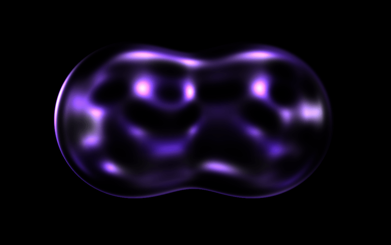
Next, let’s tune the surface appearance to make things feel more realistic.
In this demo, we’re aiming to create droplet-like metaballs. So how can we achieve that kind of look? The key idea here is to use noise to distort the surface.
To create the droplet-like texture, we’re using value noise. If you’re unfamiliar with these noise techniques, the following articles provide helpful explanations:
3D value noise is generated by interpolating random values placed at the eight vertices of a cube. The process involves three stages of linear interpolation:
Bottom face interpolation: First, we interpolate between the four corner values on the bottom face of the cube
Top face interpolation: Similarly, we interpolate between the four corner values on the top face
Final z-axis interpolation: Finally, we interpolate between the results from the bottom and top faces along the z-axis
This triple interpolation process is called trilinear interpolation.
The following code demonstrates the trilinear interpolation process for 3D value noise:
By sampling this noise using the reflection vector as coordinates, we can create a realistic water droplet-like texture. Note that we are using the surface normal obtained earlier to compute this reflection vector. To add time-based variation, we generate noise at positions offset by uTime:
It’s starting to look quite like a water droplet! However, it still appears a bit murky. To improve this, let’s add the following post-processing step:
Rendering text in WebGL opens up a whole new world of unique visual effects and creative possibilities that are often
impossible to achieve with traditional HTML, CSS and JavaScript alone. By the end of this tutorial, we’ll have created
WebGL-rendered text elements that perfectly mimic the underlying HTML structure. Since we’ll be taking an HTML-first
approach, it will be responsive, SEO-friendly and accessible. We’ll be doing every step manually so you’ll gain a
solid understanding of the principles behind merging HTML and WebGL, and text-specific stuff like how to translate CSS
styles into the 3D world.
We’ll be creating the below demo:
We’ll start off with a standard styled HTML setup. Then we’ll recreate the text elements we have inside a 3D world.
From there, we’ll position, scale and make the text responsive with the 3D space. Next, we’ll replicate the “mask
reveal effect” in WebGL. And finally, we’ll apply some scroll-driven post processing effects to the scene.
Below are the core steps we’ll follow to achieve the final result:
Create the text as a HTML element and style it regularly using CSS
Create a 3D world and recreate the text element within it
Merge the 3D and 2D world, so that we can style the 3D text by using our viewport’s dimensions
Sync the key properties like position, size and font — from the HTML element to the WebGL text element
Hide the original HTML element
Be left with only the 3D text, fully styled and positioned in sync with the hidden HTML structure
Apply animations and post-processing to enhance our 3D scene
Necessities and Prerequisites
We’ll be using the Three.js library to create the 3D world, so you should already be familiar with its basics. For the
creation of text meshes, we’ll be using the troika-three-text
library, but you don’t have to be familiar with the library beforehand. If you’ve used HTML, CSS and JavaScript, know the basics of Three.JS,
you’re good to go.
Let’s get started.
1. Creating the Regular HTML and Making it Responsive
Before diving into the WebGL and Three.js implementation, we first need to create the HTML structure that we’ll later
mimic in the 3D world. I’ve set up a very simple page with some quick responsive content — you can find the setup content
in the demo repository under index.html
and styles.css
.
HTML
:
<div class="content">
  <div class="container">
    <section class="section__heading">
      <h3 data-animation="webgl-text" class="text__2">THREE.JS</h3>
      <h2 data-animation="webgl-text" class="text__1">
        RESPONSIVE AND ACCESSIBLE TEXT
      </h2>
    </section>
    <section class="section__main__content">
      <p data-animation="webgl-text" class="text__2">
        THIS TEXT IS STYLED TO LOOK LIKE A TYPICAL BLOCK OF TEXT ON A STANDARD
        WEBSITE. BUT UNDER THE SURFACE, IT'S BEING RENDERED WITH WEBGL INSTEAD
        OF TRADITIONAL HTML.
      </p>
      <p data-animation="webgl-text" class="text__2">
        THIS OPENS THE DOOR TO CUSTOM SHADER EFFECTS AND INTERACTIONS THAT GO
        BEYOND WHAT'S POSSIBLE WITH TRADITIONAL HTML.
      </p>
      <p data-animation="webgl-text" class="text__2">
        WE KEEP THE UNDERYLING HTML STRUCTURE PRESENT IN THE DOM. RATHER THAN
        CREATING MESHES DIRECTLY IN THREE.JS, THE SCENE IS BUILT BY READING FROM
        THE EXISTING HTML CONTENT. THIS WAY, SCREEN READERS, SEARCH ENGINES, AND
        OTHER TOOLS CAN STILL INTERPRET THE PAGE AS EXPECTED.
      </p>
    </section>
    <section class="section__footer">
      <p data-animation="webgl-text" class="text__3">
        NOW GO CRAZY WITH THE SHADERS :)
      </p>
    </section>
  </div>
</div>
The <canvas>
element is set to cover the entire screen, fixed in place behind the main content. We want a full screen canvas
covering the entire screen behind our main content at all times.
All text elements intended for WebGL rendering are marked with data-animation=”webgl-text” for clarity and easy
selection when we begin scripting.
The purpose of this setup is to function as the “placeholder” that we can mimic in our 3D implementation. So, it’s
important to position and style your text at this stage
to ensure it matches the final sizing and positioning that you want to achieve. All text formatting properties like
font-size, letter-spacing, line-height etc. are the properties you want to focus on, because we’ll later read these
computed styles directly from the DOM during the WebGL phase. Color is optional here, as we can handle text coloring
later with shaders inside WebGL.
That’s it for the HTML and CSS setup! It’s all we need for the foundation to move onto our JavaScript and WebGL
implementation.
2. Initial 3D World Setup
Let’s move onto the JavaScript and WebGL implementation. I’ll be using TypeScript, but you can easily follow along
with vanilla JavaScript if you prefer. I’m assuming you’re already familiar with the basics of Three.js, so I’ll focus
on explaining the high-level setup rather than covering every detail.
Below is the starter TypeScript and Three.JS base that I’ll be using for this demo.
// main.ts

import Commons from "./classes/Commons";
import * as THREE from "three";

/**
 * Main entry-point.
 * Creates Commons and Scenes
 * Starts the update loop
 * Eventually creates Postprocessing and Texts.
  */
class App {
  private commons!: Commons;

  scene!: THREE.Scene;

  constructor() {
    document.addEventListener("DOMContentLoaded", async () => {
      await document.fonts.ready; // Important to wait for fonts to load when animating any texts.

      this.commons = Commons.getInstance();
      this.commons.init();

      this.createScene();

      this.addEventListeners();

      this.update();
    });
  }

  private createScene() {
    this.scene = new THREE.Scene();
  }

  /**
   * The main loop handler of the App
   * The update function to be called on each frame of the browser.
   * Calls update on all other parts of the app
   */
  private update() {
    this.commons.update();

    this.commons.renderer.render(this.scene, this.commons.camera);

    window.requestAnimationFrame(this.update.bind(this));
  }

  private addEventListeners() {
    window.addEventListener("resize", this.onResize.bind(this));
  }

  private onResize() {
    this.commons.onResize();
  }
}

export default new App();
// Commons.ts

import { PerspectiveCamera, WebGLRenderer, Clock } from "three";

import Lenis from "lenis";

export interface Screen {
  width: number;
  height: number;
  aspect: number;
}

export interface Sizes {
  screen: Screen;
  pixelRatio: number
}

/**
 * Singleton class for Common stuff.
 * Camera
 * Renderer
 * Lenis
 * Time
 */
export default class Commons {
  private constructor() {}

  private static instance: Commons;

  lenis!: Lenis;
  camera!: PerspectiveCamera;
  renderer!: WebGLRenderer;

  private time: Clock = new Clock();
  elapsedTime!: number;

  sizes: Sizes = {
    screen: {
      width: window.innerWidth,
      height: window.innerHeight,
      aspect: window.innerWidth / window.innerHeight,
    },
    pixelRatio: this.getPixelRatio(),
  };

  private distanceFromCamera: number = 1000;

  /**
   * Function to be called to either create Commons Singleton instance, or to return existing one.
   * TODO AFTER: Call instances init() function.
   * @returns Commons Singleton Instance.
   */
  static getInstance() {
    if (this.instance) return this.instance;

    this.instance = new Commons();
    return this.instance;
  }

  /**
   * Initializes all-things Commons. To be called after instance is set.
   */
  init() {
    this.createLenis();
    this.createCamera();
    this.createRenderer();
  }

  /**
   * Creating Lenis instance.
   * Sets autoRaf to true so we don't have to manually update Lenis on every frame.
   * Resets possible saved scroll position.
   */
  private createLenis() {
    this.lenis = new Lenis({ autoRaf: true, duration: 2 });
  }

  private createCamera() {
    this.camera = new PerspectiveCamera(
      70,
      this.sizes.screen.aspect,
      200,
      2000
    );
    this.camera.position.z = this.distanceFromCamera;
    this.camera.updateProjectionMatrix();
  }

  /**
   * createRenderer(): Creates the common WebGLRenderer to be used.
   */
  private createRenderer() {
    this.renderer = new WebGLRenderer({
      alpha: true, // Sets scene background to transparent, so our body background defines the background color
    });

    this.renderer.setSize(this.sizes.screen.width, this.sizes.screen.height);

    this.renderer.setPixelRatio(this.sizes.pixelRatio);

	  // Creating canvas element and appending to body element.
    document.body.appendChild(this.renderer.domElement);
  }

  /**
   * Single source of truth to get pixelRatio.
   */
  getPixelRatio() {
    return Math.min(window.devicePixelRatio, 2);
  }

  /**
   * Resize handler function is called from the entry-point (main.ts)
   * Updates the Common screen dimensions.
   * Updates the renderer.
   * Updates the camera.
   */
  onResize() {
    this.sizes.screen = {
      width: window.innerWidth,
      height: window.innerHeight,
      aspect: window.innerWidth / window.innerHeight,
    };
    this.sizes.pixelRatio = this.getPixelRatio();

    this.renderer.setSize(this.sizes.screen.width, this.sizes.screen.height);
    this.renderer.setPixelRatio(this.sizes.pixelRatio);

    this.onResizeCamera();
  }

  /**
   * Handler function that is called from onResize handler.
   * Updates the perspective camera with the new adjusted screen dimensions
   */
  private onResizeCamera() {
    this.camera.aspect = this.sizes.screen.aspect;
    this.camera.updateProjectionMatrix();
  }

  /**
   * Update function to be called from entry-point (main.ts)
   */
  update() {
    this.elapsedTime = this.time.getElapsedTime();
  }
}
A Note About Smooth Scroll
When syncing HTML and WebGL worlds, you should use a custom scroll
. This is because the native scroll in browsers updates the scroll position at irregular intervals and does not thus
guarantee frame-perfect updates with our requestAnimationFrame loop and our WebGL world, causing a jittery and unsynchronized movement
.
By integrating a custom scroll (Lenis in this case), we ensure our scroll updates perfectly match the frame updates of
our WebGL world.
Right now we are seeing an empty 3D world, continuously being rendered.
We’re only missing one thing to get something visible in our 3D world: the creation of the text elements. So let’s
move onto creating our WebGLText class next.
3. Creating WebGLText Class and Texts Meshes
For the creation of the text meshes, we’ll be using troika-three-text
library.
npm i troika-three-text
We’ll now create a reusable WebGLText
class
. This will handle turning each HTML element into a 3D text mesh, using Troika and our Three.js scene.
Here’s the basic setup:
// WebGLText.ts

import Commons from "./Commons";
import * as THREE from "three";

// @ts-ignore
import { Text } from "troika-three-text";

interface Props {
  scene: THREE.Scene;
  element: HTMLElement;
}

export default class WebGLText {
  commons: Commons;

  scene: THREE.Scene;
  element: HTMLElement;

  computedStyle: CSSStyleDeclaration;
  font!: string; // Path to our .ttf font file.
  bounds!: DOMRect;
  color!: THREE.Color;
  material!: THREE.ShaderMaterial;
  mesh!: Text;

  // We assign the correct font bard on our element's font weight from here
  weightToFontMap: Record<string, string> = {
    "900": "/fonts/Humane-Black.ttf",
    "800": "/fonts/Humane-ExtraBold.ttf",
    "700": "/fonts/Humane-Bold.ttf",
    "600": "/fonts/Humane-SemiBold.ttf",
    "500": "/fonts/Humane-Medium.ttf",
    "400": "/fonts/Humane-Regular.ttf",
    "300": "/fonts/Humane-Light.ttf",
    "200": "/fonts/Humane-ExtraLight.ttf",
    "100": "/fonts/Humane-Thin.ttf",
  };

  private y: number = 0; // Scroll-adjusted bounds.top

  private isVisible: boolean = false;

  constructor({ scene, element }: Props) {
    this.commons = Commons.getInstance();

    this.scene = scene;
    this.element = element;

    this.computedStyle = window.getComputedStyle(this.element); // Saving initial computed style.
  }
}
We have access to the Text class
from Troika, which allows us to create text meshes elements and apply styling to it using familiar properties like
fontSize, letterSpacing, and font. I’ll cover everything you need to style your text responsively in this tutorial,
but I implore you to take a look at the full documentation and its possibilities here
.
Troika doesn’t ship with TypeScript definitions out of the box, so if you’re using TS, you can quickly get around this
by creating a type declaration file in the root of your project. It’s not pretty, but it gets the job done while
keeping TypeScript happy.
Let’s start by creating new methods called createFont(), createColor() and createMesh().
createFont()
: Selects the appropriate .ttf file based on the DOM element’s font-weight. If a match isn’t found, we fall back to
the regular weight. Adjust the mapping to match your own font files and multiple font families if needed.
createColor()
: Converts the computed CSS color into a THREE.Color instance:
// WebGLText.ts

private createColor() {
    this.color = new THREE.Color(this.computedStyle.color);
}
createMesh():
Instantiates the text mesh and sets some basic properties. Copies the text’s inner text and sets it onto the mesh.
Adds the mesh to our Three.JS scene. We anchor the text from the left-center to match typical HTML layout
expectations.
// WebGLText.ts
private createMesh() {
  this.mesh = new Text();

  this.mesh.text = this.element.innerText; // Copying HTML content over to the mesh
  this.mesh.font = this.font;

  // Anchor the text to the left-center (instead of center-center)
  this.mesh.anchorX = "0%";
  this.mesh.anchorY = "50%";

  this.mesh.color = this.color;

  this.scene.add(this.mesh);
}
⚠️ When copying text contents over to the Mesh, avoid using innerHTML or textContent and use innerText instead as it
gives the most layout-accurate and consistent results.
setStaticValues
(): Let’s also create a baby setStaticValues() method which will set the critical properties of our text mesh based on
the computedStyle.
We sets values like font size based on computed CSS. We’ll expand this more as we sync more styles down the line.
We want to call all these methods in the constructor like this:
Finally, let’s update our App class (main.ts), and hook this all up by scanning for DOM elements with a
data-animation=”webgl-text” attribute — creating a WebGLText instance for each one:
// main.ts

texts!: Array<WebGLText>;

// ...

private createWebGLTexts() {
  const texts = document.querySelectorAll('[data-animation="webgl-text"]');

  if (texts) {
    this.texts = Array.from(texts).map((el) => {
      const newEl = new WebGLText({
        element: el as HTMLElement,
        scene: this.scene,
      });

      return newEl;
    });
  }
}
Make sure to call this method in the constructor on initialization. This will populate our scene with styled text
meshes based on our DOM content.
That’s all we need to have our text meshes visible, it’s not the prettiest sight to behold, but at least we got
everything working:
Next Challenge: Screen vs. 3D Space Mismatch
Even though we copy the font size directly from the DOM, the scale looks different in 3D. That’s because WebGL units don’t map 1:1 with screen pixels
, and they operate in different coordinate systems. This mismatch will become even more obvious if we start
positioning and animating elements.
To get true visual parity between our DOM elements and WebGL text, we need to bridge the gap between screen space and
3D space. Let’s tackle that next so our text sizes and positions actually match with what we see in the browser.
4. Syncing Dimensions
The major problem when syncing HTML and WebGL dimensions is that things between them aren’t exactly pixel-perfect.
This is because the DOM and WebGL don’t “speak the same units” by default.
Web browsers work in screen pixels.
WebGL uses arbitrary units
Our goal is simple:
💡 Make one unit in the WebGL scene equal one pixel on the screen.
To achieve this, we’ll adjust the camera’s field of view (FOV) so that visible area through the camera exactly matches
the dimensions of the browser window in pixels.
So, we’ll create a syncDimensions()
function under our Commons class, which calculates our camera’s field of view such that 1 unit in the WebGL scene
corresponds to 1 pixel on the screen — at a given distance from the camera.
 // Commons.ts
/**
  * Helper function that is called upon creation and resize
  * Updates the camera's fov according to the new dimensions such that the window's pixels match with that of WebGL scene
  */
private syncDimensions() {
  this.camera.fov =
    2 *
    Math.atan(this.sizes.screen.height / 2 / this.distanceFromCamera) *
    (180 / Math.PI);
}
This function will be called once when we create the camera, and every time that the screen is resized.
Let’s break down what’s actually going on here using the image below:
We know:
The height of the screen
The distance from camera (Z)
The FOV of the camera is the vertical angle (fov y in the image)
So our main goal is to set how wide (vertical angle) we see according to our screen height.
Because the Z (distance from camera) and half of the screen height forms a right triangle
(distance + height), we can solve for the angle using some basic trigonometry, and compute the FOV using the inverse
tangent ( atan
) of this triangle.
Step-by-step Breakdown of the Formula
this.sizes.screen.height / 2
→ This gives us half the screen’s pixel height — the opposite side of our triangle.
this.distanceFromCamera
→ This is the adjacent side of the triangle — the distance from the camera to the 3D scene.
Math.atan(opposite / adjacent)
→ Calculates half of the vertical FOV (in radians).
*2
→ Since atan only gives half of the angle, we multiply it by 2 to get the full FOV.
* (180 / Math.PI)
→ Converts the angle from radians to degrees (Three.js expects degrees for PerspectiveCamera’s fov)
That’s all we need to sync our dimensions, and this setup ensures that 1 unit in WebGL = 1 pixel on screen.
Let’s move back to the text implementation.
5. Setting Text Properties and Positioning
Now that we’ve synced the WebGL scene to our screen’s pixel dimensions, we can start mapping HTML styles to our 3D
text.
If everything’s wired up correctly, you should see that the font size of the WebGL-rendered text matches the size of
the underlying HTML, although the positioning is still off.
Let’s sync more styling properties and positioning.
Before we can position the 3D text, we need to get the DOM element’s position and size. We’ll create a new method in
the WebGLText class called createBounds() ,
and use the browser’s built-in getBoundingClientRect() method:
Next, we’ll pull important typographic properties from the DOM (computed style) and pass them to the 3D mesh, so that
it behaves like our native HTML text. (Again, you can see the full documentation and possible properties of troika here
). Below I’ve included the most important ones.
  // WebGLText.ts

private setStaticValues() {
  const { fontSize, letterSpacing, lineHeight, whiteSpace, textAlign } =
    this.computedStyle;

  const fontSizeNum = window.parseFloat(fontSize);

  this.mesh.fontSize = fontSizeNum;

  this.mesh.textAlign = textAlign;

  // Troika defines letter spacing in em's, so we convert to them
  this.mesh.letterSpacing = parseFloat(letterSpacing) / fontSizeNum;

  // Same with line height
  this.mesh.lineHeight = parseFloat(lineHeight) / fontSizeNum;

  // Important to define maxWidth for the mesh, so that our text doesn't overflow
  this.mesh.maxWidth = this.bounds.width;

  // Match whiteSpace behavior (e.g., 'pre', 'nowrap')
  this.mesh.whiteSpace = whiteSpace;
}
Troika accepts some of the properties in local em units, so we have to convert pixels into em’s by dividing the pixel
values by the font size.
Also, it’s important to set a maximum width (in pixels) to constrain the mesh’s layout — this prevents text from
overflowing and ensures proper text wrapping.
And finally, let’s create an update()
function to be called on each frame that consistently positions our mesh according to the underlying DOM position.
And now, the texts will perfectly follow DOM counterparts
, even as the user scrolls.
Let’s finalize our base text class implementation before diving into effects:
Resizing
We need to ensure that our WebGL text updates correctly on window resize events. This means recreating the computedStyle, bounds, and static values
whenever the window size changes.
Once everything is working responsively and perfectly synced with the DOM, we can finally hide the original HTML text by setting it transparent
— but we’ll keep it in place so it’s still selectable and accessible to the user.
// WebGLText.ts

this.createFont();
this.createColor();
this.createBounds();
this.createMesh();
this.setStaticValues();

this.element.style.color = "transparent"; // Hide DOM element
We should now have our perfectly responsive text meshes, and the user only sees the rendered WebGL text, while the DOM
element remains fully intact for accessibility.
Let’s add some effects!
6. Adding a Custom shader and Replicating Mask Reveal Animations
Troika also lets us use custom shader materials for meshes, giving us the flexibility to create complex effects beyond
just setting colors.
The vertex shader passes the texture coordinates (uv) to the fragment shader for the text rendering.
Shader File Imports using Vite
To handle shader files more easily, we can use the vite-plugin-glsl
plugin together with Vite to directly import shader files like .frag and .vert in code:
Let’s now create our custom ShaderMaterial and apply it to our mesh:
// WebGLText.ts

// Importing shaders
import fragmentShader from "../../shaders/text/text.frag";
import vertexShader from "../../shaders/text/text.vert";

//...

this.createFont();
this.createColor();
this.createBounds();
this.createMaterial(); // Creating material
this.createMesh();
this.setStaticValues();

//...

private createMaterial() {
   this.material = new THREE.ShaderMaterial({
     fragmentShader,
     vertexShader
       uniforms: {
       uColor: new THREE.Uniform(this.color), // Passing our color to the shader
     },
   });
 }
In the createMaterial()
method, we define the ShaderMaterial
using the imported shaders and pass in the uColor uniform, which allows us to dynamically control the color of the
text based on our DOM-element.
And now, instead of setting the color directly on the default mesh material, we apply our new custom material:
  // WebGLText.ts

private createMesh() {
  this.mesh = new Text();

  this.mesh.text = this.element.innerText; // Always use innerText (not innerHTML or textContent).
  this.mesh.font = this.font;

  this.mesh.anchorX = "0%";
  this.mesh.anchorY = "50%";

  this.mesh.material = this.material; //Using custom material instead of color
}
At this point, we are using our custom shader material, but so far, nothing in our output has changed. Let’s now setup
show and hide animations using our custom shader, and replicate the mask reveal effect.
Setting up Reveal Animations
We’ll create an animation that uses a progress uniform (uProgress) to control the visibility and reveal progress of
the text. The animation will be controlled using the motion library.
First, we must install motion
and import its animate
and inView
functions to our WebGLText class.
npm i motion
// WebGLText.ts

import { inView, animate } from "motion";
Now, let’s configure our class so that when the text steps into view, the show() function is called
, and when it steps away, the hide() function is called
. These methods also control the current visibility variable this.isVisible
. These functions will control the uProgress variable, and animate it between 0 and 1.
For this, we also must setup an addEventListeners() function:
 // WebGLText.ts

/**
  * Inits visibility tracking using motion's inView function.
  * Show is called when the element steps into view, and hide is called when the element steps out of view
  */
private addEventListeners() {
  inView(this.element, () => {
    this.show();

    return () => this.hide();
  });
}

show() {
  this.isVisible = true;

  animate(
    this.material.uniforms.uProgress,
    { value: 1 },
    { duration: 1.8, ease: [0.25, 1, 0.5, 1] }
  );
}

hide() {
  animate(
    this.material.uniforms.uProgress,
    { value: 0 },
    { duration: 1.8, onComplete: () => (this.isVisible = false) }
  );
}
Just make sure to call addEventListeners() in your constructor after setting up the class.
Updating the Shader Material for Animation
We’ll also add two additional uniform variables in our material for the animations:
uProgress
: Controls the reveal progress (from 0 to 1).
uHeight
: Used by the vertex shader to calculate vertical position offset.
Updated createMaterial()
method:
 // WebGLText.ts

private createMaterial() {
  this.material = new THREE.ShaderMaterial({
    fragmentShader,
    vertexShader,
    uniforms: {
      uProgress: new THREE.Uniform(0),
      uHeight: new THREE.Uniform(this.bounds.height),
      uColor: new THREE.Uniform(this.color),
    },
  });
}
Since the uHeight is dependent on bounds, we also want to update the uniform variable upon resizing:
We now have the text class instance automatically calling show() and hide(), and animating the uProgress according to
the visibility of our underlying DOM-element.
For performance, you might want to update the update() method to only calculate a new position when the mesh is
visible:
Creating a mask reveal effect with custom shaders in WebGL is surprisingly simple when we break it down into two
separate movements: one happening in the fragment shader and the other in the vertex shader. You might’ve seen this
effect happen in WebGL on the page of Zajno
, for example.
Instead of overcomplicating the concept with complex masks or thinking about “lifting it up” behind a window (as we do
in traditional HTML), we can think of it as two distinct actions that work together.
Fragment Shader
: We clip the text vertically, revealing it gradually from top to bottom.
Vertex Shader
: We translate the text’s position from the bottom to the top by its height.
Together these two movements create the illusion of the text lifting itself up from behind a mask.
Let’s update our fragment shader code:
//text.frag

uniform float uProgress; // Our progress value between 0 and 1

uniform vec3 uColor;
varying vec2 vUv;

void main() {
  // Calculate the reveal threshold (bottom to top reveal)
  float reveal = 1.0 - vUv.y;

  // Discard fragments above the reveal threshold based on progress
  if (reveal > uProgress) discard;

  // Apply the color to the visible parts of the text
  gl_FragColor = vec4(uColor, 1.0);
}
When uProgress is 0, the mesh is fully clipped out, and nothing is visible
When uProgress increases towards 1, the mesh reveals itself from top to bottom.
For the vertex shader, we can simply pass the new uniform called uHeight, which stands for the height of our
DOM-element (this.bounds.height), and translate the output vertically according to it and uProgress.
//text.vert

uniform float uProgress;
uniform float uHeight; // Total height of the mesh passed in from JS

varying vec2 vUv;

void main() {
  vUv = uv;

  vec3 transformedPosition = position;

  // Push the mesh upward as it reveals
  transformedPosition.y -= uHeight * (1.0 - uProgress);

  gl_Position = projectionMatrix * modelViewMatrix * vec4(transformedPosition, 1.0);
}
uHeight
: Total height of the DOM-element (and mesh), passed in from JS.
When uProgress
is 0
, the mesh is fully pushed down.
As uProgress
reaches 1
, it resolves to its natural position.
Now, we should have a beautifully on-scroll animating scene, where the texts reveal themselves as in regular HTML when
they scroll into view.
To spice things up, let’s add some scroll-velocity based post processing effects to our scene as the final step!
7. Adding Post-processing
Now that we’ve built our animated WebGL text with custom shaders and scroll-triggered reveals, we can push the visuals
further with post-processing
.
Post-processing allows us to apply full-screen visual effects after the scene has been rendered. This is done by
passing the final image through a series of custom shader passes.
So, in this final section, we’ll:
Set up a PostProcessing class using Three.js’s EffectComposer
Add a custom RGB shift and wave distortion effect
Drive the distortion strength dynamically using the scroll velocity from our Lenis custom scroll instance
Creating a PostProcessing class with EffectComposer
Let’s create a PostProcessing class that will be intialized from our entry-point, and which will handle everything
regarding postprocessing using Three.JS’s EffectComposer. Read more about the EffectComposer class here from Three.js’s documentation
. We’ll also create new fragment and vertex shaders for the postprocessing class to use.
// PostProcessing.ts

import {
  EffectComposer,
  RenderPass,
  ShaderPass,
} from "three/examples/jsm/Addons.js";
import Commons from "./Commons";
import * as THREE from "three";

// Importing postprocessing shaders
import fragmentShader from "../../shaders/postprocessing/postprocessing.frag";
import vertexShader from "../../shaders/postprocessing/postprocessing.vert";

interface Props {
  scene: THREE.Scene;
}

export default class PostProcessing {
  // Scene and utility references
  private commons: Commons;
  private scene: THREE.Scene;

  private composer!: EffectComposer;

  private renderPass!: RenderPass;
  private shiftPass!: ShaderPass;

  constructor({ scene }: Props) {
    this.commons = Commons.getInstance();

    this.scene = scene;

    this.createComposer();
    this.createPasses();
  }

  private createComposer() {
    this.composer = new EffectComposer(this.commons.renderer);
    this.composer.setPixelRatio(this.commons.sizes.pixelRatio);
    this.composer.setSize(
      this.commons.sizes.screen.width,
      this.commons.sizes.screen.height
    );
  }

  private createPasses() {
    // Creating Render Pass (final output) first.
    this.renderPass = new RenderPass(this.scene, this.commons.camera);
    this.composer.addPass(this.renderPass);

    // Creating Post-processing shader for wave and RGB-shift effect.
    const shiftShader = {
      uniforms: {
        tDiffuse: { value: null },      // Default input from previous pass
        uVelocity: { value: 0 },        // Scroll velocity input
        uTime: { value: 0 },            // Elapsed time for animated distortion
      },
      vertexShader,
      fragmentShader,
    };

    this.shiftPass = new ShaderPass(shiftShader);
    this.composer.addPass(this.shiftPass);
  }

  /**
   * Resize handler for EffectComposer, called from entry-point.
   */
  onResize() {
    this.composer.setPixelRatio(this.commons.sizes.pixelRatio);
    this.composer.setSize(
      this.commons.sizes.screen.width,
      this.commons.sizes.screen.height
    );
  }

  update() {
    this.shiftPass.uniforms.uTime.value = this.commons.elapsedTime;

    this.composer.render();
  }
}
Since we don’t have our postprocessing shaders created yet, make sure you create placeholder postprocessing.frag and
postprocessing.vert shaders so the imports don’t fail.
Constructor:
Initializes the class by storing the provided scene, grabbing the shared Commons instance, and then calling createComposer()
and createPasses()
.
createComposer():
Sets up the EffectComposer with the correct pixel ratio and canvas size:
EffectComposer wraps the WebGL renderer and allows chaining of multiple render passes.
Sized according to current viewport dimensions and pixel ratio
createPasses():
This method sets up all rendering passes applied to the scene.
RenderPass
: The first pass that simply renders the scene with the main camera as regular.
ShaderPass (shiftPass)
: A custom full-screen shader pass that we’ll create and which will create the RGB shift and wavy distortion
effects.
update():
Method called on every frame. Updates the uTime uniform so we can animate effects over time, and renders the final
post-processed image using composer.render()
Initializing Post-processing
To wire the post-processing system into our existing app, we update our main.ts:
  //main.ts
private postProcessing!: PostProcessing;

//....

constructor() {
  document.addEventListener("DOMContentLoaded", async () => {
    await document.fonts.ready;

    this.commons = Commons.getInstance();
    this.commons.init();

    this.createScene();
    this.createWebGLTexts();
    this.createPostProcessing(); // Creating post-processing
    this.addEventListeners();

    this.update();
  });
}

// ...

private createPostProcessing() {
  this.postProcessing = new PostProcessing({ scene: this.scene });
}

// ...

private update() {
  this.commons.update();

  if (this.texts) {
    this.texts.forEach((el) => el.update());
  }

  // Don't need line below as we're rendering everything using EffectComposer.
  // this.commons.renderer.render(this.scene, this.commons.camera);

  this.postProcessing.update(); // Post-processing class handles rendering of output from now on


  window.requestAnimationFrame(this.update.bind(this));
}


private onResize() {
  this.commons.onResize();

  if (this.texts) {
    this.texts.forEach((el) => el.onResize());
  }

  this.postProcessing.onResize(); // Resize post-processing
}
So in the new update() function, instead of rendering directly from there, we now hand off rendering responsibility to
the PostProcessing class.
Creating Post-processing Shader and Wiring Scroll Velocity
We want to modify the PostProcessing class further, so that we update the postprocessing fragment shader with the
current scroll velocity from Lenis.
For this, I’m adding a new property lerpedVelocity and lerpFactor, which control the smoothed out velocity. The raw
velocity values from lenis can be spiky and sudden, especially with fast scrolling or scroll jumps. If we pass that
raw value directly into a shader, it can cause a really jittery output.
private lerpedVelocity = 0; // Smoothed scroll velocity for post-processing.
private lerpFactor = 0.05; // Controls how quickly lerpedVelocity follows the real velocity

// ...

update() {
    this.shiftPass.uniforms.uTime.value = this.commons.elapsedTime;

  // Reading current velocity form lenis instance.
  const targetVelocity = this.commons.lenis.velocity;

  // We use the lerped velocity as the actual velocity for the shader, just for a smoother experience.
  this.lerpedVelocity +=
    (targetVelocity - this.lerpedVelocity) * this.lerpFactor;

  this.shiftPass.uniforms.uVelocity.value = this.lerpedVelocity;

  this.composer.render();
}
Post-processing Shaders
For the vertex shader, we can keep all things default, we pass the texture coordinates to the fragment shader.
The red channel is offset slightly based on the velocity, creating the RGB shift effect.
// Applying the RGB shift to the wave-distorted coordinates
float r = texture2D(tDiffuse, vec2(waveUv.x, waveUv.y + uVelocity * 0.0005)).r;
vec2 gb = texture2D(tDiffuse, waveUv).gb;

gl_FragColor = vec4(r, gb, r);
This will create a subtle color separation in the final image that shifts according to our scroll velocity.
Finally, we combine red, green, blue, and alpha into the output color.
8. Final Result
And there you have it! We’ve created a responsive text scene, with scroll-triggered mask reveal animations and
wavy/rgb shifted post-processing.
This setup provides a solid, modular foundation for building more advanced WebGL text effects. If you’re curious to explore further, consider adding particles, fluid simulations, audio reactivity, or more complex materials and shaders. If you’re interested in breakdowns of any of these, feel free to reach out on X.
A simple way to improve efficiency is knowing your IDE shortcuts. Let’s learn how to create custom ones to generate code automatically.
Table of Contents
Just a second! 🫷 If you are here, it means that you are a software developer.
So, you know that storage, networking, and domain management have a cost .
If you want to support this blog, please ensure that you have disabled the adblocker for this site. I configured Google AdSense to show as few ADS as possible – I don’t want to bother you with lots of ads, but I still need to add some to pay for the resources for my site.
Thank you for your understanding. – Davide
One of the best tricks to boost productivity is knowing your tools.
I’m pretty sure you’ve already used some predefined snippets in Visual Studio. For example, when you type ctor and hit Tab twice, VS automatically creates an empty constructor for the current class.
In this article, we will learn how to create custom snippets: in particular, we will design a snippet that automatically creates a C# Unit Test method with some placeholders and predefined Arrange-Act-Assert blocks.
Snippet Designer: a Visual Studio 2022 extension to add a UI to your placeholders
Snippets are defined in XML-like files with .snippet extension. But we all know that working with XMLs can be cumbersome, especially if you don’t have a clear idea of the expected structure.
Therefore, even if not strictly necessary, I suggest installing a VS2022 extension called Snippet Designer 2022.
This extension, developed by Matthew Manela, can be found on GitHub, where you can view the source code.
This extension gives you a UI to customize the snippet instead of manually editing the XML nodes. It allows you to customize the snippet, the related metadata, and even the placeholders.
Create a basic snippet in VS2022 using a .snippet file
As we saw, snippets are defined in a simple XML.
In order to have your snippets immediately available in Visual Studio, I suggest you create those files in a specific VS2022 folder under the path \Documents\Visual Studio 2022\Code Snippets\Visual C#\My Code Snippets\.
So, create an empty file, change its extension to .snippet, and save it to that location.
Now, you can open Visual Studio (it’s not necessary to open a project, but I’d recommend you to do so). Then, head to File > Open, and open the file you saved under the My Code Snippets directory.
Thanks to Snippet Designer, you will be able to see a nice UI instead of plain XML content.
Have a look at how I filled in the several parts to create a snippet that generates a variable named x, assigns to it a value, and then calls x++;
Have a look at the main parts:
the body, which contains the snippet to be generated;
the top layer, where we specified:
the Snippet name: Int100; it’s the display name of the shortcut
the code language: C#;
the shortcut: int100; it’s the string you’ll type in that allows you to generate the expected snippet;
the bottom table, which contains the placeholders used in the snippet; more on this later;
the properties tab, on the sidebar: here is where you specify some additional metadata, such as:
Author, Description, and Help Url of the snippet, in case you want to export it;
the kind of snippet: possible values are MethodBody, MethodDecl and TypeDecl. However, this value is supported only in Visual Basic.
Now, hit save and be ready to import it!
Just for completeness, here’s the resulting XML:
<?xml version="1.0" encoding="utf-8"?><CodeSnippetsxmlns="http://schemas.microsoft.com/VisualStudio/2005/CodeSnippet"><CodeSnippetFormat="1.0.0"><Header><SnippetTypes><SnippetType>Expansion</SnippetType></SnippetTypes><Title>Int100</Title><Author></Author><Description></Description><HelpUrl></HelpUrl><Shortcut>int100</Shortcut></Header><Snippet><CodeKind="method decl"Language="csharp"Delimiter="$"><![CDATA[int x = 100;
x++;]]></Code></Snippet></CodeSnippet></CodeSnippets>
Notice that the actual content of the snippet is defined in the CDATA block.
Import the snippet in Visual Studio
It’s time to import the snippet. Open the Tools menu item and click on Code Snippets Manager.
From here, you can import a snippet by clicking the Import… button. Given that we’ve already saved our snippet in the correct folder, we’ll find it under the My Code Snippets folder.
Now it’s ready! Open a C# class, and start typing int100. You’ll see our snippet in the autocomplete list.
By hitting Tab twice, you’ll see the snippet’s content being generated.
How to use placeholders when defining snippets in Visual Studio
Wouldn’t it be nice to have the possibility to define customizable parts of your snippets?
Let’s see a real example: I want to create a snippet to create the structure of a Unit Tests method with these characteristics:
it already contains the AAA (Arrange, Act, Assert) sections;
the method name should follow the pattern “SOMETHING should DO STUFF when CONDITION”. I want to be able to replace the different parts of the method name by using placeholders.
You can define placeholders using the $ symbol. You will then see the placeholders in the table at the bottom of the UI. In this example, the placeholders are $TestMethod$, $DoSomething$, and $Condition$. I also added a description to explain the purpose of each placeholder better.
The XML looks like this:
<?xml version="1.0" encoding="utf-8"?><CodeSnippetsxmlns="http://schemas.microsoft.com/VisualStudio/2005/CodeSnippet"><CodeSnippetFormat="1.0.0"><Header><SnippetTypes><SnippetType>Expansion</SnippetType></SnippetTypes><Title>Test Sync</Title><Author>Davide Bellone</Author><Description>Scaffold the AAA structure for synchronous NUnit tests</Description><HelpUrl></HelpUrl><Shortcut>testsync</Shortcut></Header><Snippet><Declarations><LiteralEditable="true"><ID>TestMethod</ID><ToolTip>Name of the method to be tested</ToolTip><Default>TestMethod</Default><Function></Function></Literal><LiteralEditable="true"><ID>DoSomething</ID><ToolTip>Expected behavior or result</ToolTip><Default>DoSomething</Default><Function></Function></Literal><LiteralEditable="true"><ID>Condition</ID><ToolTip>Initial conditions</ToolTip><Default>Condition</Default><Function></Function></Literal></Declarations><CodeLanguage="csharp"Delimiter="$"Kind="method decl"><![CDATA[[Test]
public void $TestMethod$_Should_$DoSomething$_When_$Condition$()
{
// Arrange
// Act
// Assert
}]]></Code></Snippet></CodeSnippet></CodeSnippets>
Now, import it as we already did before.
Then, head to your code, start typing testsync, and you’ll see the snippet come to life. The placeholders we defined are highlighted. You can then fill in these placeholders, hit tab, and move to the next one.
Bonus: how to view all the snippets defined in VS
If you want to learn more about your IDE and the available snippets, you can have a look at the Snippet Explorer table.
You can find it under View > Tools > Snippet Explorer.
Here, you can see all the snippets, their shortcuts, and the content of each snippet. You can also see the placeholders highlighted in green.
It’s always an excellent place to learn more about Visual Studio.
Further readings
As always, you can read more on Microsoft Docs. It’s a valuable resource, although I find it difficult to follow.
There are some tips that may improve both the code quality and the developer productivity.
If you want to enforce some structures or rules, add such snippets in your repository; when somebody joins your team, teach them how to import those snippets.
I hope you enjoyed this article! Let’s keep in touch on Twitter or LinkedIn! 🤜🤛