In unit tests, sometimes you need to perform deep checks on the object passed to the mocked service. We will learn 3 ways to do that with Moq and C#
Table of Contents
Just a second! 🫷 If you are here, it means that you are a software developer.
So, you know that storage, networking, and domain management have a cost .
If you want to support this blog, please ensure that you have disabled the adblocker for this site. I configured Google AdSense to show as few ADS as possible – I don’t want to bother you with lots of ads, but I still need to add some to pay for the resources for my site.
Thank you for your understanding. – Davide
When writing unit tests, you can use Mocks to simulate the usage of class dependencies.
Even though some developers are harshly against the usage of mocks, they can be useful, especially when the mocked operation does not return any value, but still, you want to check that you’ve called a specific method with the correct values.
In this article, we will learn 3 ways to check the values passed to the mocks when using Moq in our C# Unit Tests.
To better explain those 3 ways, I created this method:
publicvoid UpdateUser(User user, Preference preference)
{
var userDto = new UserDto
{
Id = user.id,
UserName = user.username,
LikesBeer = preference.likesBeer,
LikesCoke = preference.likesCoke,
LikesPizza = preference.likesPizza,
};
_userRepository.Update(userDto);
}
UpdateUser simply accepts two objects, user and preference, combines them into a single UserDto object, and then calls the Update method of _userRepository, which is an interface injected in the class constructor.
As you can see, we are not interested in the return value from _userRepository.Update. Rather, we are interested in checking that we are calling it with the right values.
We can do it in 3 ways.
Verify each property with It.Is
The simplest, most common way is by using It.Is<T> within the Verify method.
This approach works well when you have to perform checks on only a few fields. But the more fields you add, the longer and messier that code becomes.
Also, a problem with this approach is that if it fails, it becomes hard to understand which is the cause of the failure, because there is no indication of the specific field that did not match the expectations.
Here’s an example of an error message:
Expected invocation on the mock at least once, but was never performed: _ => _.Update(It.Is<UserDto>(u => (((u.Id == 1 && u.UserName == "Davidde") && u.LikesPizza == True) && u.LikesBeer == True) && u.LikesCoke == False))

Performed invocations:

Mock<IUserRepository:1> (_):
    IUserRepository.Update(UserDto { UserName = Davide, Id = 1, LikesPizza = True, LikesCoke = False, LikesBeer = True })
Can you spot the error? And what if you were checking 15 fields instead of 5?
Verify with external function
Another approach is by externalizing the function.
[Test]publicvoid WithExternalFunction()
{
//Arrangevar user = new User(1, "Davide");
var preferences = new Preference(true, true, false);
UserDto expected = new UserDto
{
Id = 1,
UserName = "Davide",
LikesBeer = true,
LikesCoke = false,
LikesPizza = true,
};
//Act userUpdater.UpdateUser(user, preferences);
//Assert userRepo.Verify(_ => _.Update(It.Is<UserDto>(u => AreEqual(u, expected))));
}
privatebool AreEqual(UserDto u, UserDto expected)
{
Assert.AreEqual(expected.UserName, u.UserName);
Assert.AreEqual(expected.Id, u.Id);
Assert.AreEqual(expected.LikesBeer, u.LikesBeer);
Assert.AreEqual(expected.LikesCoke, u.LikesCoke);
Assert.AreEqual(expected.LikesPizza, u.LikesPizza);
returntrue;
}
Here, we are passing an external function to the It.Is<T> method.
This approach allows us to define more explicit and comprehensive checks.
The good parts of it are that you will gain more control over the assertions, and you will also have better error messages in case a test fails:
Expected string length 6 but was 7. Strings differ at index 5.
Expected: "Davide"
But was:  "Davidde"
The bad part is that you will stuff your test class with lots of different methods, and the class can easily become hard to maintain. Unluckily, we cannot use local functions.
On the other hand, having external functions allows us to combine them when we need to do some tests that can be reused across test cases.
Intercepting the function parameters with Callback
Lastly, we can use a hidden gem of Moq: Callbacks.
With Callbacks, you can store in a local variable the reference to the item that was called by the method.
[Test]publicvoid CompareWithCallback()
{
// Arrangevar user = new User(1, "Davide");
var preferences = new Preference(true, true, false);
UserDto actual = null;
userRepo.Setup(_ => _.Update(It.IsAny<UserDto>()))
.Callback(new InvocationAction(i => actual = (UserDto)i.Arguments[0]));
UserDto expected = new UserDto
{
Id = 1,
UserName = "Davide",
LikesBeer = true,
LikesCoke = false,
LikesPizza = true,
};
//Act userUpdater.UpdateUser(user, preferences);
//Assert Assert.IsTrue(AreEqual(expected, actual));
}
In this way, you can use it locally and run assertions directly to that object without relying on the Verify method.
Or, if you use records, you can use the auto-equality checks to simplify the Verify method as I did in the previous example.
Wrapping up
In this article, we’ve explored 3 ways to perform checks on the objects passed to dependencies mocked with Moq.
Each way has its pros and cons, and it’s up to you to choose the approach that fits you the best.
I personally prefer the second and third approaches, as they allow me to perform better checks on the passed values.
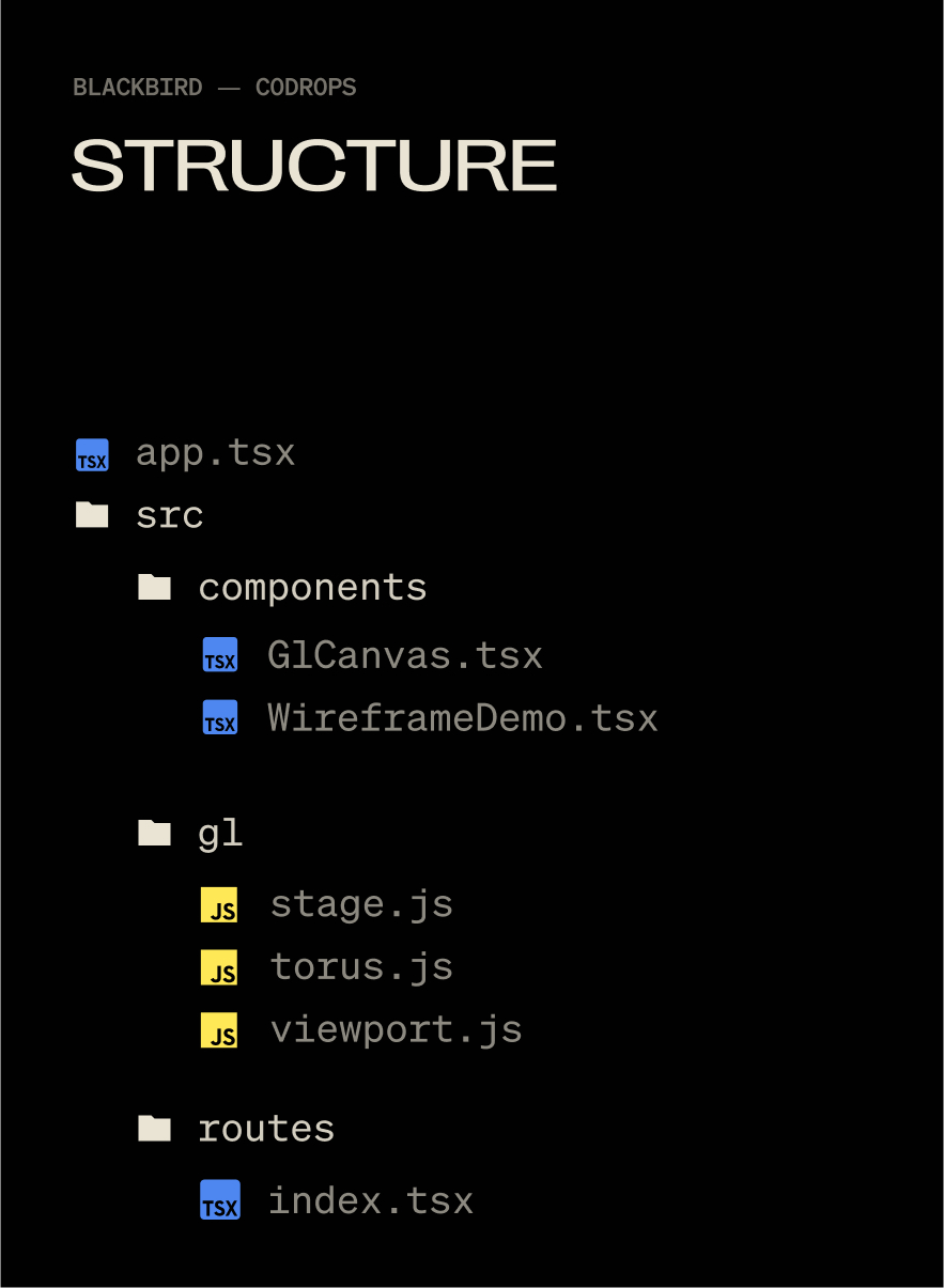
Blackbird was a fun, experimental site that I used as a way to get familiar with WebGL inside of Solid.js. It went through the story of how the SR-71 was built in super technical detail. The wireframe effect covered here helped visualize the technology beneath the surface of the SR-71 while keeping the polished metal exterior visible that matched the sites aesthetic.
Here is how the effect looks like on the Blackbird site:
In this tutorial, we’ll rebuild that effect from scratch: rendering a model twice, once as a solid and once as a wireframe, then blending the two together in a shader for a smooth, animated transition. The end result is a flexible technique you can use for technical reveals, holograms, or any moment where you want to show both the structure and the surface of a 3D object.
There are three things at work here: material properties, render targets, and a black-to-white shader gradient. Let’s get into it!
But First, a Little About Solid.js
Solid.js isn’t a framework name you hear often, I’ve switched my personal work to it for the ridiculously minimal developer experience and because JSX remains the greatest thing since sliced bread. You absolutely don’t need to use the Solid.js part of this demo, you could strip it out and use vanilla JS all the same. But who knows, you may enjoy it 🙂
TLDR: Full-stack JSX without all of the opinions of Next and Nuxt, plus it’s like 8kb gzipped, wild.
The technical version: Written in JSX, but doesn’t use a virtual DOM, so a “reactive” (think useState()) doesn’t re-render an entire component, just one DOM node. Also runs isomorphically, so "use client" is a thing of the past.
Setting Up Our Scene
We don’t need anything wild for the effect: a Mesh, Camera, Renderer, and Scene will do. I use a base Stage class (for theatrical-ish naming) to control when things get initialized.
A Global Object for Tracking Window Dimensions
window.innerWidth and window.innerHeight trigger document reflow when you use them (more about document reflow here). So I keep them in one object, only updating it when necessary and reading from the object, instead of using window and causing reflow. Notice these are all set to 0 and not actual values by default. window gets evaluated as undefined when using SSR, so we want to wait to set this until our app is mounted, GL class is initialized, and window is defined to avoid everybody’s favorite error: Cannot read properties of undefined (reading ‘window’).
Before we can render anything, we need a small framework to handle our scene setup, rendering loop, and resizing logic. Instead of scattering this across multiple files, we’ll wrap it in a Stage class that initializes the camera, renderer, and scene in one place. This makes it easier to keep our WebGL lifecycle organized, especially once we start adding more complex objects and effects.
// src/gl/stage.js

import { WebGLRenderer, Scene, PerspectiveCamera } from 'three';
import { viewport, resizeViewport } from './viewport';

class Stage {
  init(element) {
    resizeViewport() // Set the initial viewport dimensions, helps to avoid using window inside of viewport.js for SSR-friendliness

    this.camera = new PerspectiveCamera(45, viewport.aspectRatio, 0.1, 1000);
    this.camera.position.set(0, 0, 2); // back the camera up 2 units so it isn't on top of the meshes we make later, you won't see them otherwise.

    this.renderer = new WebGLRenderer();
    this.renderer.setSize(viewport.width, viewport.height);
    element.appendChild(this.renderer.domElement); // attach the renderer to the dom so our canvas shows up

    this.renderer.setPixelRatio(viewport.devicePixelRatio); // Renders higher pixel ratios for screens that require it.

    this.scene = new Scene();
  }

  render() {
    this.renderer.render(this.scene, this.camera);
    requestAnimationFrame(this.render.bind(this));
// All of the scenes child classes with a render method will have it called automatically
    this.scene.children.forEach((child) => {
      if (child.render && typeof child.render === 'function') {
        child.render();
      }
    });
  }

  resize() {
    this.renderer.setSize(viewport.width, viewport.height);
    this.camera.aspect = viewport.aspectRatio;
    this.camera.updateProjectionMatrix();

// All of the scenes child classes with a resize method will have it called automatically
    this.scene.children.forEach((child) => {
      if (child.resize && typeof child.resize === 'function') {
        child.resize();
      }
    });
  }
}

export default new Stage();
And a Fancy Mesh to Go With It
With our stage ready, we can give it something interesting to render. A torus knot is perfect for this: it has plenty of curves and detail to show off both the wireframe and solid passes. We’ll start with a simple MeshNormalMaterial in wireframe mode so we can clearly see its structure before moving on to the blended shader version.
// src/gl/torus.js

import { Mesh, MeshBasicMaterial, TorusKnotGeometry } from 'three';

export default class Torus extends Mesh {
  constructor() {
    super();

    this.geometry = new TorusKnotGeometry(1, 0.285, 300, 26);
    this.material = new MeshNormalMaterial({
      color: 0xffff00,
      wireframe: true,
    });

    this.position.set(0, 0, -8); // Back up the mesh from the camera so its visible
  }
}
A quick note on lights
For simplicity we’re using MeshNormalMaterial so we don’t have to mess with lights. The original effect on Blackbird had six lights, waaay too many. The GPU on my M1 Max was choked to 30fps trying to render the complex models and realtime six-point lighting. But reducing this to just 2 lights (which visually looked identical) ran at 120fps no problem. Three.js isn’t like Blender where you can plop in 14 lights and torture your beefy computer with the render for 12 hours while you sleep. The lights in WebGL have consequences 🫠
Now, the Solid JSX Components to House It All
// src/components/GlCanvas.tsx

import { onMount, onCleanup } from 'solid-js';
import Stage from '~/gl/stage';

export default function GlCanvas() {
// let is used instead of refs, these aren't reactive
  let el;
  let gl;
  let observer;

  onMount(() => {
    if(!el) return
    gl = Stage;

    gl.init(el);
    gl.render();


    observer = new ResizeObserver((entry) => gl.resize());
    observer.observe(el); // use ResizeObserver instead of the window resize event.
    // It is debounced AND fires once when initialized, no need to call resize() onMount
  });

  onCleanup(() => {
    if (observer) {
      observer.disconnect();
    }
  });


  return (
    <div
      ref={el}
      style={{
        position: 'fixed',
        inset: 0,
        height: '100lvh',
        width: '100vw',
      }}

    />
  );
}
let is used to declare a ref, there is no formal useRef() function in Solid. Signals are the only reactive method. Read more on refs in Solid.
Then slap that component into app.tsx:
// src/app.tsx

import { Router } from '@solidjs/router';
import { FileRoutes } from '@solidjs/start/router';
import { Suspense } from 'solid-js';
import GlCanvas from './components/GlCanvas';

export default function App() {
  return (
    <Router
      root={(props) => (
        <Suspense>
          {props.children}
          <GlCanvas />
        </Suspense>
      )}
    >
      <FileRoutes />
    </Router>
  );
}
Each 3D piece I use is tied to a specific element on the page (usually for timeline and scrolling), so I create an individual component to control each class. This helps me keep organized when I have 5 or 6 WebGL moments on one page.
// src/components/WireframeDemo.tsx

import { createEffect, createSignal, onMount } from 'solid-js'
import Stage from '~/gl/stage';
import Torus from '~/gl/torus';

export default function WireframeDemo() {
  let el;
  const [element, setElement] = createSignal(null);
  const [actor, setActor] = createSignal(null);

  createEffect(() => {
    setElement(el);
    if (!element()) return;

    setActor(new Torus()); // Stage is initialized when the page initially mounts,
    // so it's not available until the next tick.
    // A signal forces this update to the next tick,
    // after Stage is available.

    Stage.scene.add(actor());
  });

  return <div ref={el} />;
}
createEffect() instead of onMount(): this automatically tracks dependencies (element, and actor in this case) and fires the function when they change, no more useEffect() with dependency arrays 🙃. Read more on createEffect in Solid.
Then a minimal route to put the component on:
// src/routes/index.tsx

import WireframeDemo from '~/components/WiframeDemo';

export default function Home() {
  return (
    <main>
      <WireframeDemo />
    </main>
  );
}
Now you’ll see this:
Switching a Material to Wireframe
I loved wireframe styling for the Blackbird site! It fit the prototype feel of the story, fully textured models felt too clean, wireframes are a bit “dirtier” and unpolished. You can wireframe just about any material in Three.js with this:
But we want to do this dynamically on only part of our model, not on the entire thing.
Enter render targets.
The Fun Part: Render Targets
Render Targets are a super deep topic but they boil down to this: Whatever you see on screen is a frame for your GPU to render, in WebGL you can export that frame and re-use it as a texture on another mesh, you are creating a “target” for your rendered output, a render target.
Since we’re going to need two of these targets, we can make a single class and re-use it.
// src/gl/render-target.js

import { WebGLRenderTarget } from 'three';
import { viewport } from '../viewport';
import Torus from '../torus';
import Stage from '../stage';

export default class RenderTarget extends WebGLRenderTarget {
  constructor() {
    super();

    this.width = viewport.width * viewport.devicePixelRatio;
    this.height = viewport.height * viewport.devicePixelRatio;
  }

  resize() {
    const w = viewport.width * viewport.devicePixelRatio;
    const h = viewport.height * viewport.devicePixelRatio;

    this.setSize(w, h)
  }
}
This is just an output for a texture, nothing more.
Now we can make the class that will consume these outputs. It’s a lot of classes, I know, but splitting up individual units like this helps me keep track of where stuff happens. 800 line spaghetti mega-classes are the stuff of nightmares when debugging WebGL.
// src/gl/targeted-torus.js

import {
  Mesh,
  MeshNormalMaterial,
  PerspectiveCamera,
  PlaneGeometry,
} from 'three';
import Torus from './torus';
import { viewport } from './viewport';
import RenderTarget from './render-target';
import Stage from './stage';

export default class TargetedTorus extends Mesh {
  targetSolid = new RenderTarget();
  targetWireframe = new RenderTarget();

  scene = new Torus(); // The shape we created earlier
  camera = new PerspectiveCamera(45, viewport.aspectRatio, 0.1, 1000);

  constructor() {
    super();

    this.geometry = new PlaneGeometry(1, 1);
    this.material = new MeshNormalMaterial();
  }

  resize() {
    this.targetSolid.resize();
    this.targetWireframe.resize();

    this.camera.aspect = viewport.aspectRatio;
    this.camera.updateProjectionMatrix();
  }
}
Now, switch our WireframeDemo.tsx component to use the TargetedTorus class, instead of Torus:
// src/components/WireframeDemo.tsx

import { createEffect, createSignal, onMount } from 'solid-js';
import Stage from '~/gl/stage';
import TargetedTorus from '~/gl/targeted-torus';

export default function WireframeDemo() {
  let el;
  const [element, setElement] = createSignal(null);
  const [actor, setActor] = createSignal(null);

  createEffect(() => {
    setElement(el);
    if (!element()) return;

    setActor(new TargetedTorus()); // << change me

    Stage.scene.add(actor());
  });

  return <div ref={el} data-gl="wireframe" />;
}
“Now all I see is a blue square Nathan, it feel like we’re going backwards, show me the cool shape again”.
Shhhhh, It’s by design I swear!
From MeshNormalMaterial to ShaderMaterial
We can now take our Torus rendered output and smack it onto the blue plane as a texture using ShaderMaterial. MeshNormalMaterial doesn’t let us use a texture, and we’ll need shaders soon anyway. Inside of targeted-torus.js remove the MeshNormalMaterial and switch this in:
THE TORUS IS BACK. We’ve passed our image texture into the shader and its outputting our original render.
Mixing Wireframe and Solid Materials with Shaders
Shaders were black magic to me before this project. It was my first time using them in production and I’m used to frontend where you think in boxes. Shaders are coordinates 0 to 1, which I find far harder to understand. But, I’d used Photoshop and After Effects with layers plenty of times. These applications do a lot of the same work shaders can: GPU computing. This made it far easier. Starting out by picturing or drawing what I wanted, thinking how I might do it in Photoshop, then asking myself how I could do it with shaders. Photoshop or AE into shaders is far less mentally taxing when you don’t have a deep foundation in shaders.
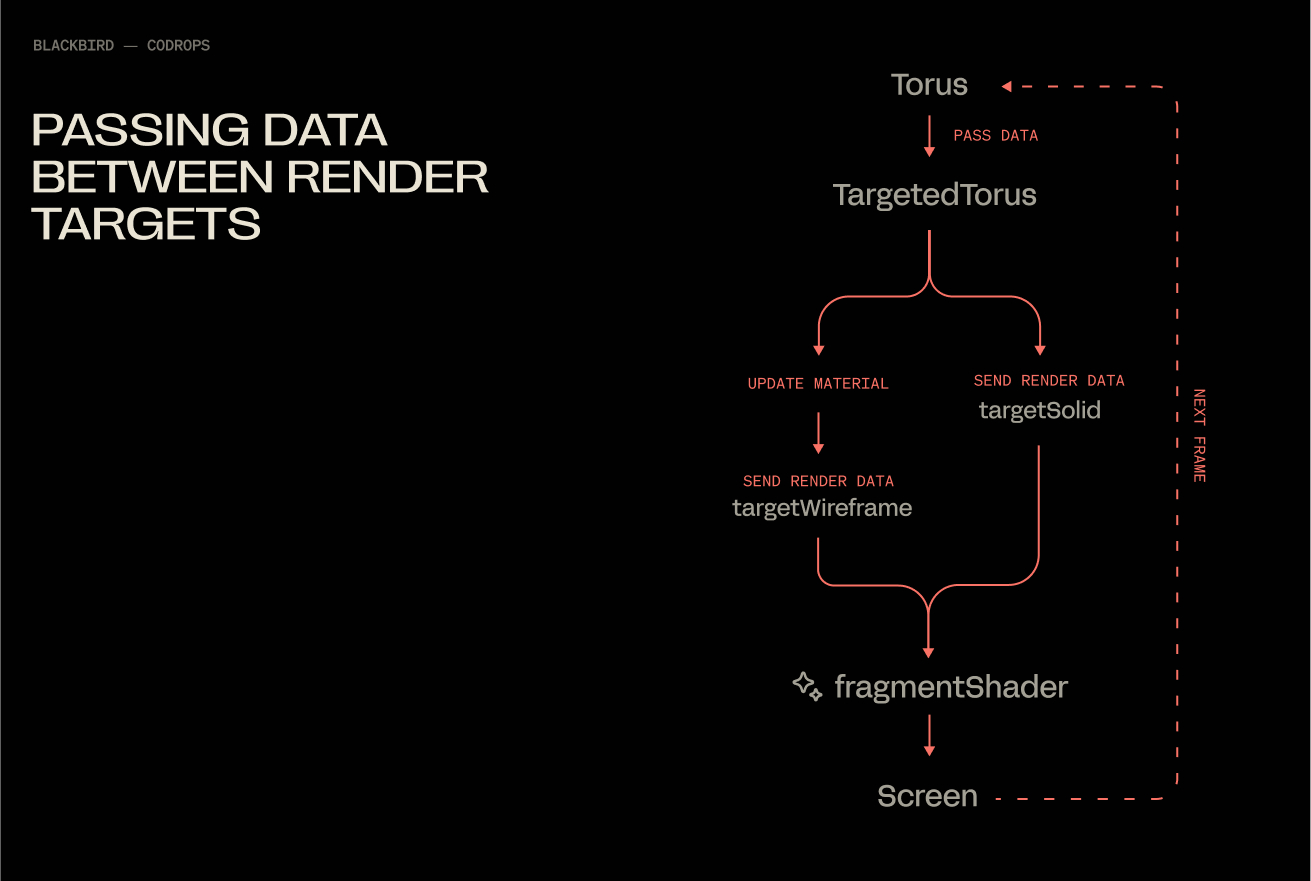
Populating Both Render Targets
At the moment, we are only saving data to the solidTarget render target via normals. We will update our render loop, so that our shader has them both this and wireframeTarget available simultaneously.
With this, you end up with a flow that under the hood looks like this:
Fading Between Two Textures
Our fragment shader will get a little update, 2 additions:
smoothstep creates a linear ramp between 2 values. UVs only go from 0 to 1, so in this case we use .15 and .65 as the limits (they look make the effect more obvious than 0 and 1). Then we use the x value of the uvs to define which value gets fed into smoothstep.
vec4 mixed = mix(wireframe_texture, solid_texture, blend); mix does exactly what it says, mixes 2 values together at a ratio determined by blend. .5 being a perfectly even split.
Congratulations, you’ve officially spent a measurable portion of your day blending two materials together. It was worth it though, wasn’t it? At the very least, I hope this saved you some of the mental gymnastics orchestrating a pair of render targets.
APIs often call other APIs to perform operations. If an error occurs in one of them, how can you understand the context that caused that error? You can use Correlation IDs in your logs!
Table of Contents
Just a second! 🫷 If you are here, it means that you are a software developer.
So, you know that storage, networking, and domain management have a cost .
If you want to support this blog, please ensure that you have disabled the adblocker for this site. I configured Google AdSense to show as few ADS as possible – I don’t want to bother you with lots of ads, but I still need to add some to pay for the resources for my site.
Thank you for your understanding. – Davide
Correlation IDs are values that are passed across different systems to correlate the operations performed during a “macro” operation.
Most of the time they are passed as HTTP Headers – of course in systems that communicate via HTTP.
In this article, we will learn how to log those Correlation IDs using Serilog, a popular library that helps handle logs in .NET applications.
Setting up the demo dotNET project
This article is heavily code-oriented. So, let me first describe the demo project.
Overview of the project
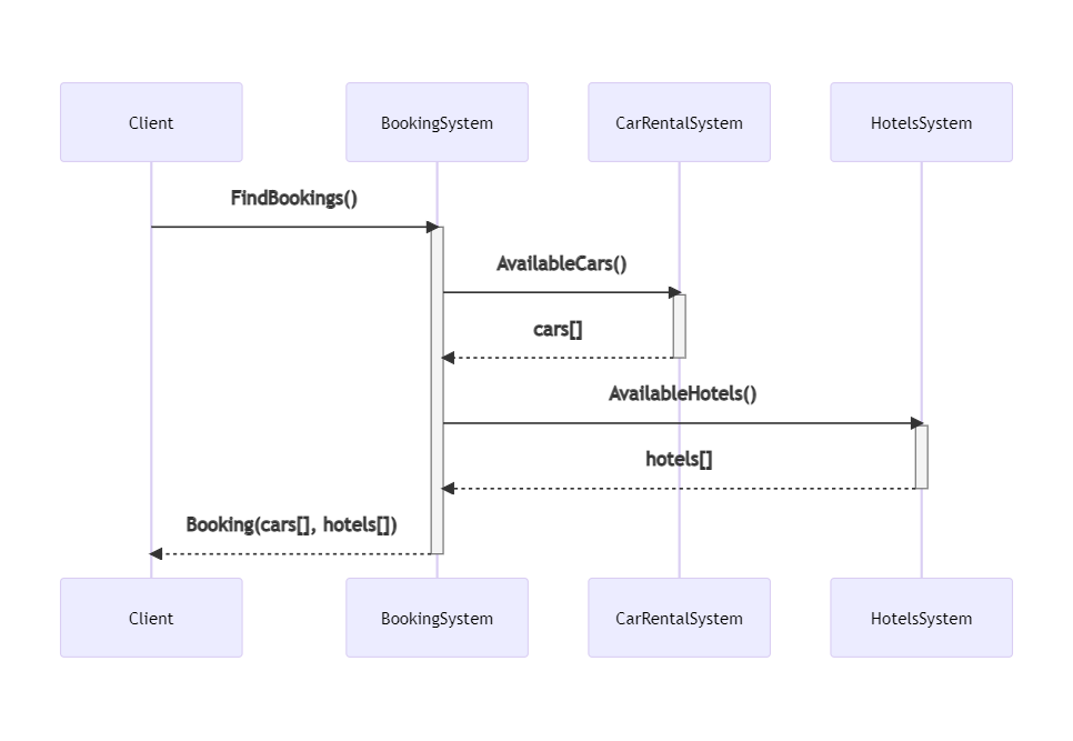
To demonstrate how to log Correlation IDs and how to correlate logs generated by different systems, I’ve created a simple solution that handles bookings for a trip.
The “main” project, BookingSystem, fetches data from external systems by calling some HTTP endpoints; it then manipulates the data and returns an aggregate object to the caller.
BookingSystem depends on two projects, placed within the same solution: CarRentalSystem, which returns data about the available cars in a specified date range, and HotelsSystem, which does the same for hotels.
So, this is the data flow:
If an error occurs in any of those systems, can we understand the full story of the failed request? No. Unless we use Correlation IDs!
Let’s see how to add them and how to log them.
We need to propagate HTTP Headers. You could implement it from scratch, as we’ve seen in a previous article. Or we could use a native library that does it all for us.
Of course, let’s go with the second approach.
For every project that will propagate HTTP headers, we have to follow these steps.
First, we need to install Microsoft.AspNetCore.HeaderPropagation: this NuGet package allows us to add the .NET classes needed to propagate HTTP headers.
Next, we have to update the part of the project that we use to configure our application. For .NET projects with Minimal APIs, it’s the Program class.
Here we need to add the capability to read the HTTP Context, by using
builder.Services.AddHttpContextAccessor();
As you can imagine, this is needed because, to propagate HTTP Headers, we need to know which are the incoming HTTP Headers. And they can be read from the HttpContext object.
Next, we need to specify, as a generic behavior, which headers must be propagated. For instance, to propagate the “my-custom-correlation-id” header, you must add
Since you probably know what’s going on, let me go straight to the point.
Install Serilog Enricher for Correlation IDs
We’re gonna use a specific library to log HTTP Headers treating them as Correlation IDs. To use it, you have to install the Serilog.Enrichers.CorrelationId package available on NuGet.
Therefore, you can simply run
dotnet add Serilog.Enrichers.CorrelationId
to every .NET project that will use this functionality.
Once we have that NuGet package ready, we can add its functionality to our logger by adding this line:
This simple line tells dotnet that, when we see an HTTP Header named “my-custom-correlation-id”, we should log it as a Correlation ID.
Run it all together
Now we have everything in place – it’s time to run it!
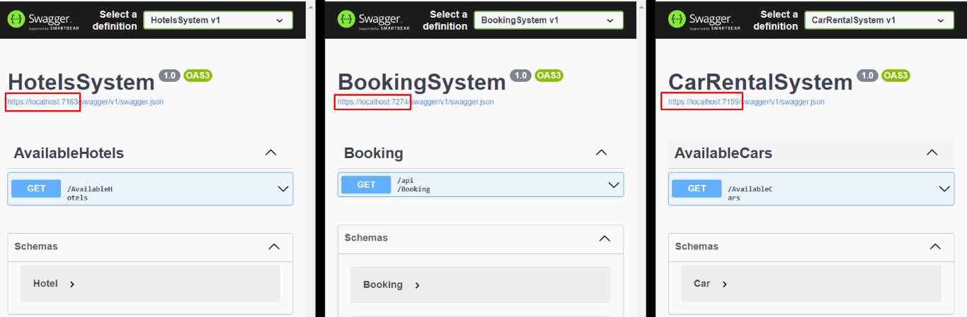
We have to run all the 3 services at the same time (you can do it with VisualStudio or you can run them separately using a CMD), and we need to have Seq installed on our local machine.
You will see 3 instances of Swagger, and each instance is running under a different port.
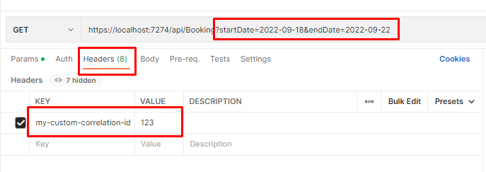
Once we have all the 3 applications up and running, we can call the /Bookings endpoint passing it a date range and an HTTP Header with key “my-custom-correlation-id” and value = “123” (or whatever we want).
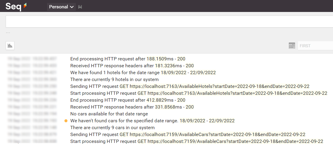
If everything worked as expected, we can open Seq and see all the logs we’ve written in our applications:
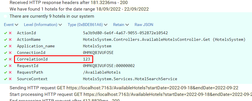
Open one of them and have a look at the attributes of the logs: you will see a CorrelationId field with the value set to “123”.
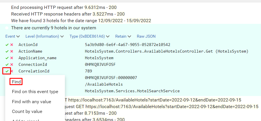
Now, to better demonstrate how it works, call the endpoint again, but this time set “789” as my-custom-correlation-id, and specify a different date range. You should be able to see another set of logs generated by this second call.
You can now apply filters to see which logs are related to a specific Correlation ID: open one log, click on the tick button and select “Find”.
You will then see all and only logs that were generated during the call with header my-custom-correlation-id set to “789”.
Further readings
That’s it. With just a few lines of code, you can dramatically improve your logging strategy.
For this article, we’ve used the Microsoft.AspNetCore.HeaderPropagation package, which is ready to use. Are you interested in building your own solution – or, at least, learning how you can do that?
This article concludes a sort of imaginary path that taught us how to use Serilog, how to correlate different logs within the same application using Scopes, and how to correlate logs from different services using Correlation IDs.
Using these capabilities, you will be able to write logs that can help you understand the context in which a specific log occurred, thus helping you fix errors more efficiently.
The idea is to go from the monument to the church with a car. The flag marks the middle, between the two points.
The solution uses several powerful Python libraries:
OSMnx to download and work with real road networks from OpenStreetMap
NetworkX to model the road system as a graph and calculate the shortest path using Dijkstra’s algorithm
Folium for interactive map visualization
We start by geocoding the two landmarks to get their latitude and longitude. Then we build a drivable street network centered around the Levski Monument using ox.graph_from_address. After snapping both points to the nearest graph nodes, we compute the shortest route by distance. Finally, we visualize everything both in an interactive map and in a clean black-on-white static graph where the path is drawn in yellow.
Exposing Swagger UI is a good way to help developers consume your APIs. But don’t be boring: customize your UI with some fancy CSS
Table of Contents
Just a second! 🫷 If you are here, it means that you are a software developer.
So, you know that storage, networking, and domain management have a cost .
If you want to support this blog, please ensure that you have disabled the adblocker for this site. I configured Google AdSense to show as few ADS as possible – I don’t want to bother you with lots of ads, but I still need to add some to pay for the resources for my site.
Thank you for your understanding. – Davide
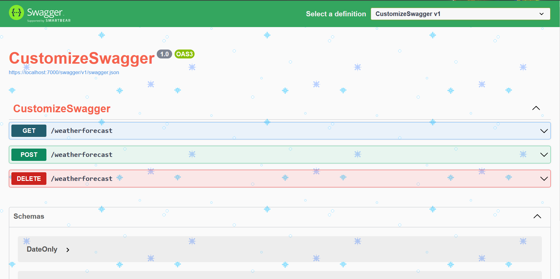
Brace yourself, Christmas is coming! 🎅
If you want to add a more festive look to your Swagger UI, it’s just a matter of creating a CSS file and injecting it.
You should create a custom CSS for your Swagger endpoints, especially if you are exposing them outside your company: if your company has a recognizable color palette, using it in your Swagger pages can make your brand stand out.
In this article, we will learn how to inject a CSS file in the Swagger UI generated using .NET Minimal APIs.
How to add Swagger in your .NET Minimal APIs
There are plenty of tutorials about how to add Swagger to your APIs. I wrote some too, where I explained how every configuration impacts what you see in the UI.
That article was targeting older dotNET versions without Minimal APIs. Now everything’s easier.
When you create your API project, Visual Studio asks you if you want to add OpenAPI support (aka Swagger). By adding it, you will have everything in place to get started with Swagger.
The key parts are builder.Services.AddEndpointsApiExplorer(), builder.Services.AddSwaggerGen(), app.UseSwagger(), app.UseSwaggerUI() and WithOpenApi(). Do you know that those methods do? If so, drop a comment below! 📩
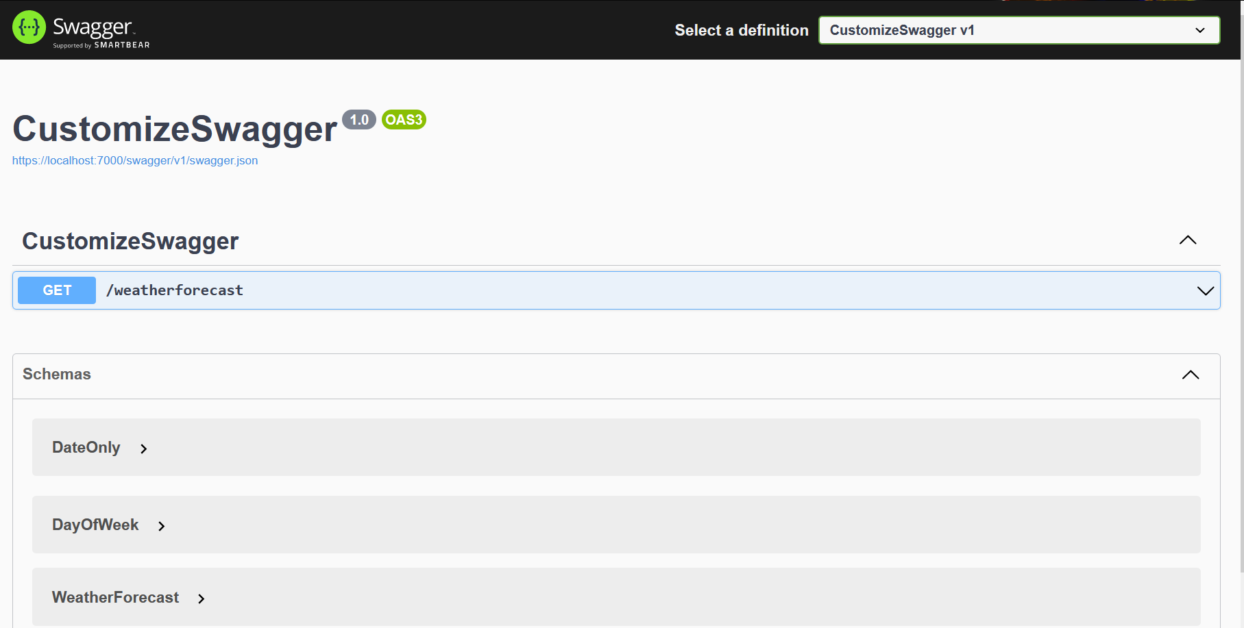
Now, if we run our application, we will see a UI similar to the one below.
That’s a basic UI. Quite boring, uh? Let’s add some style
Create the CSS file for Swagger theming
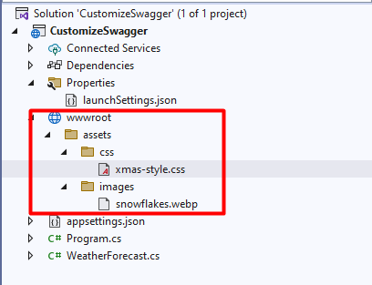
All the static assets must be stored within the wwwroot folder. It does not exist by default, so you have to create it manually. Click on the API project, add a new folder, and name it “wwwroot”. Since it’s a special folder, by default Visual Studio will show it with a special icon (it’s a sort of blue world, similar to 🌐).
Now you can add all the folders and static resources needed.
I’ve created a single CSS file under /wwwroot/assets/css/xmas-style.css. Of course, name it as you wish – as long as it is within the wwwroot folder, it’s fine.
the element selectors are taken directly from the Swagger UI – you’ll need a bit of reverse-engineering skills: just open the Browser Console and find the elements you want to update;
unless the element does not already have the rule you want to apply, you have to add the !important CSS operator. Otherwise, your code won’t affect the UI;
you can add assets from other folders: I’ve added background-image: url("../images/snowflakes.webp"); to the body style. That image is, as you can imagine, under the wwwroot folder we created before.
Just as a recap, here’s my project structure:
Of course, it’s not enough: we have to tell Swagger to take into consideration that file
How to inject a CSS file in Swagger UI
This part is quite simple: you have to update the UseSwaggerUI command within the Main method:
CSS is not the only part you can customize, there’s way more. Here’s an article I wrote about Swagger integration in .NET Core 3 APIs, but it’s still relevant (I hope! 😁)
Theming is often not considered an important part of API development. That’s generally correct: why should I bother adding some fancy colors to APIs that are not expected to have a UI?
This makes sense if you’re working on private APIs. In fact, theming is often useful to improve brand recognition for public-facing APIs.
You should also consider using theming when deploying APIs to different environments: maybe Blue for Development, Yellow for Staging, and Green for Production. That way your developers can understand which environment they’re exploring right easily.
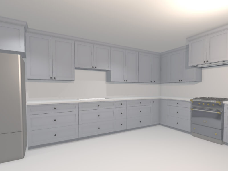
Back in November 2024, I shared a post on X about a tool I was building to help visualize kitchen remodels. The response from the Three.js community was overwhelmingly positive. The demo showed how procedural rendering techniques—often used in games—can be applied to real-world use cases like designing and rendering an entire kitchen in under 60 seconds.
In this article, I’ll walk through the process and thinking behind building this kind of procedural 3D kitchen design tool using vanilla Three.js and TypeScript—from drawing walls and defining cabinet segments to auto-generating full kitchen layouts. Along the way, I’ll share key technical choices, lessons learned, and ideas for where this could evolve next.
Have been wanting to redesign my parents’ kitchen for a while now
…so I built them a little 3D kitchen design-tool with @threejs, so they can quickly prototype floorplans/ideas
Here’s me designing a full kitchen remodel in ~60s 🙂
You can try out an interactive demo of the latest version here: https://kitchen-designer-demo.vercel.app/. (Tip: Press the “/” key to toggle between 2D and 3D views.)
Designing Room Layouts with Walls
Example of user drawing a simple room shape using the built-in wall module.
To initiate our project, we begin with the wall drawing module. At a high level, this is akin to Figma’s pen tool, where the user can add one line segment at a time until a closed—or open-ended—polygon is complete on an infinite 2D canvas. In our build, each line segment represents a single wall as a 2D plane from coordinate A to coordinate B, while the complete polygon outlines the perimeter envelope of a room.
We begin by capturing the [X, Z] coordinates (with Y oriented upwards) of the user’s initial click on the infinite floor plane. This 2D point is obtained via Three.js’s built-in raycaster for intersection detection, establishing Point A.
As the user hovers the cursor over a new spot on the floor, we apply the same intersection logic to determine a temporary Point B. During this movement, a preview line segment appears, connecting the fixed Point A to the dynamic Point B for visual feedback.
Upon the user’s second click to confirm Point B, we append the line segment (defined by Points A and B) to an array of segments. The former Point B instantly becomes the new Point A, allowing us to continue the drawing process with additional line segments.
Here is a simplified code snippet demonstrating a basic 2D pen-draw tool using Three.js:
import * as THREE from 'three';

const scene = new THREE.Scene();
const camera = new THREE.PerspectiveCamera(75, window.innerWidth / window.innerHeight, 0.1, 1000);
camera.position.set(0, 5, 10); // Position camera above the floor looking down
camera.lookAt(0, 0, 0);

const renderer = new THREE.WebGLRenderer();
renderer.setSize(window.innerWidth, window.innerHeight);
document.body.appendChild(renderer.domElement);

// Create an infinite floor plane for raycasting
const floorGeometry = new THREE.PlaneGeometry(100, 100);
const floorMaterial = new THREE.MeshBasicMaterial({ color: 0xcccccc, side: THREE.DoubleSide });
const floor = new THREE.Mesh(floorGeometry, floorMaterial);
floor.rotation.x = -Math.PI / 2; // Lay flat on XZ plane
scene.add(floor);

const raycaster = new THREE.Raycaster();
const mouse = new THREE.Vector2();
let points: THREE.Vector3[] = []; // i.e. wall endpoints
let tempLine: THREE.Line | null = null;
const walls: THREE.Line[] = [];

function getFloorIntersection(event: MouseEvent): THREE.Vector3 | null {
  mouse.x = (event.clientX / window.innerWidth) * 2 - 1;
  mouse.y = -(event.clientY / window.innerHeight) * 2 + 1;
  raycaster.setFromCamera(mouse, camera);
  const intersects = raycaster.intersectObject(floor);
  if (intersects.length > 0) {
    // Round to simplify coordinates (optional for cleaner drawing)
    const point = intersects[0].point;
    point.x = Math.round(point.x);
    point.z = Math.round(point.z);
    point.y = 0; // Ensure on floor plane
    return point;
  }
  return null;
}

// Update temporary line preview
function onMouseMove(event: MouseEvent) {
  const point = getFloorIntersection(event);
  if (point && points.length > 0) {
    // Remove old temp line if exists
    if (tempLine) {
      scene.remove(tempLine);
      tempLine = null;
    }
    // Create new temp line from last point to current hover
    const geometry = new THREE.BufferGeometry().setFromPoints([points[points.length - 1], point]);
    const material = new THREE.LineBasicMaterial({ color: 0x0000ff }); // Blue for temp
    tempLine = new THREE.Line(geometry, material);
    scene.add(tempLine);
  }
}

// Add a new point and draw permanent wall segment
function onMouseDown(event: MouseEvent) {
  if (event.button !== 0) return; // Left click only
  const point = getFloorIntersection(event);
  if (point) {
    points.push(point);
    if (points.length > 1) {
      // Draw permanent wall line from previous to current point
      const geometry = new THREE.BufferGeometry().setFromPoints([points[points.length - 2], points[points.length - 1]]);
      const material = new THREE.LineBasicMaterial({ color: 0xff0000 }); // Red for permanent
      const wall = new THREE.Line(geometry, material);
      scene.add(wall);
      walls.push(wall);
    }
    // Remove temp line after click
    if (tempLine) {
      scene.remove(tempLine);
      tempLine = null;
    }
  }
}

// Add event listeners
window.addEventListener('mousemove', onMouseMove);
window.addEventListener('mousedown', onMouseDown);

// Animation loop
function animate() {
  requestAnimationFrame(animate);
  renderer.render(scene, camera);
}
animate();
The above code snippet is a very basic 2D pen tool, and yet this information is enough to generate an entire room instance. For reference: not only does each line segment represent a wall (2D plane), but the set of accumulated points can also be used to auto-generate the room’s floor mesh, and likewise the ceiling mesh (the inverse of the floor mesh).
In order to view the planes representing the walls in 3D, one can transform each THREE.Line into a custom Wall class object, which contains both a line (for orthogonal 2D “floor plan” view) and a 2D inward-facing plane (for perspective 3D “room” view). To build this class:
class Wall extends THREE.Group {
  constructor(length: number, height: number = 96, thickness: number = 4) {
    super();

    // 2D line for top view, along the x-axis
    const lineGeometry = new THREE.BufferGeometry().setFromPoints([
      new THREE.Vector3(0, 0, 0),
      new THREE.Vector3(length, 0, 0),
    ]);
    const lineMaterial = new THREE.LineBasicMaterial({ color: 0xff0000 });
    const line = new THREE.Line(lineGeometry, lineMaterial);
    this.add(line);

    // 3D wall as a box for thickness
    const wallGeometry = new THREE.BoxGeometry(length, height, thickness);
    const wallMaterial = new THREE.MeshBasicMaterial({ color: 0xaaaaaa, side: THREE.DoubleSide });
    const wall = new THREE.Mesh(wallGeometry, wallMaterial);
    wall.position.set(length / 2, height / 2, 0);
    this.add(wall);
  }
}
We can now update the wall draw module to utilize this newly created Wall object:
// Update our variables
let tempWall: Wall | null = null;
const walls: Wall[] = [];

// Replace line creation in onMouseDown with
if (points.length > 1) {
  const start = points[points.length - 2];
  const end = points[points.length - 1];
  const direction = end.clone().sub(start);
  const length = direction.length();
  const wall = new Wall(length);
  wall.position.copy(start);
  wall.rotation.y = Math.atan2(direction.z, direction.x); // Align along direction (assuming CCW for inward facing)
  scene.add(wall);
  walls.push(wall);
}
Upon adding the floor and ceiling meshes, we can further transform our wall module into a room generation module. To recap what we have just created: by adding walls one by one, we have given the user the ability to create full rooms with walls, floors, and ceilings—all of which can be adjusted later in the scene.
User dragging out the wall in 3D perspective camera-view.
Generating Cabinets with Procedural Modeling
Our cabinet-related logic can consist of countertops, base cabinets, and wall cabinets.
Rather than taking several minutes to add the cabinets on a case-by-case basis—for example, like with IKEA’s 3D kitchen builder—it’s possible to add all the cabinets at once via a single user action. One method to employ here is to allow the user to draw high-level cabinet line segments, in the same manner as the wall draw module.
In this module, each cabinet segment will transform into a linear row of base and wall cabinets, along with a parametrically generated countertop mesh on top of the base cabinets. As the user creates the segments, we can automatically populate this line segment with pre-made 3D cabinet meshes in meshing software like Blender. Ultimately, each cabinet’s width, depth, and height parameters will be fixed, while the width of the last cabinet can be dynamic to fill the remaining space. We use a cabinet filler piece mesh here—a regular plank, with its scale-X parameter stretched or compressed as needed.
Creating the Cabinet Line Segments
User can make a half-peninsula shape by dragging the cabinetry line segments alongside the walls, then in free-space.
Here we will construct a dedicated cabinet module, with the aforementioned cabinet line segment logic. This process is very similar to the wall drawing mechanism, where users can draw straight lines on the floor plane using mouse clicks to define both start and end points. Unlike walls, which can be represented by simple thin lines, cabinet line segments need to account for a standard depth of 24 inches to represent the base cabinets’ footprint. These segments do not require closing-polygon logic, as they can be standalone rows or L-shapes, as is common in most kitchen layouts.
We can further improve the user experience by incorporating snapping functionality, where the endpoints of a cabinet line segment automatically align to nearby wall endpoints or wall intersections, if within a certain threshold (e.g., 4 inches). This ensures cabinets fit snugly against walls without requiring manual precision. For simplicity, we’ll outline the snapping logic in code but focus on the core drawing functionality.
We can start by defining the CabinetSegment class. Like the walls, this should be its own class, as we will later add the auto-populating 3D cabinet models.
class CabinetSegment extends THREE.Group {
  public length: number;

  constructor(length: number, height: number = 96, depth: number = 24, color: number = 0xff0000) {
    super();
    this.length = length;
    const geometry = new THREE.BoxGeometry(length, height, depth);
    const material = new THREE.MeshBasicMaterial({ color, wireframe: true });
    const box = new THREE.Mesh(geometry, material);
    box.position.set(length / 2, height / 2, depth / 2); // Shift so depth spans 0 to depth (inward)
    this.add(box);
  }
}
Once we have the cabinet segment, we can use it in a manner very similar to the wall line segments:
let cabinetPoints: THREE.Vector3[] = [];
let tempCabinet: CabinetSegment | null = null;
const cabinetSegments: CabinetSegment[] = [];
const CABINET_DEPTH = 24; // everything in inches
const CABINET_SEGMENT_HEIGHT = 96; // i.e. both wall & base cabinets -> group should extend to ceiling
const SNAPPING_DISTANCE = 4;

function getSnappedPoint(point: THREE.Vector3): THREE.Vector3 {
  // Simple snapping: check against existing wall points (wallPoints array from wall module)
  for (const wallPoint of wallPoints) {
    if (point.distanceTo(wallPoint) < SNAPPING_DISTANCE) return wallPoint;
  }
  return point;
}

// Update temporary cabinet preview
function onMouseMoveCabinet(event: MouseEvent) {
  const point = getFloorIntersection(event);
  if (point && cabinetPoints.length > 0) {
    const snappedPoint = getSnappedPoint(point);
    if (tempCabinet) {
      scene.remove(tempCabinet);
      tempCabinet = null;
    }
    const start = cabinetPoints[cabinetPoints.length - 1];
    const direction = snappedPoint.clone().sub(start);
    const length = direction.length();
    if (length > 0) {
      tempCabinet = new CabinetSegment(length, CABINET_SEGMENT_HEIGHT, CABINET_DEPTH, 0x0000ff); // Blue for temp
      tempCabinet.position.copy(start);
      tempCabinet.rotation.y = Math.atan2(direction.z, direction.x);
      scene.add(tempCabinet);
    }
  }
}

// Add a new point and draw permanent cabinet segment
function onMouseDownCabinet(event: MouseEvent) {
  if (event.button !== 0) return;
  const point = getFloorIntersection(event);
  if (point) {
    const snappedPoint = getSnappedPoint(point);
    cabinetPoints.push(snappedPoint);
    if (cabinetPoints.length > 1) {
      const start = cabinetPoints[cabinetPoints.length - 2];
      const end = cabinetPoints[cabinetPoints.length - 1];
      const direction = end.clone().sub(start);
      const length = direction.length();
      if (length > 0) {
        const segment = new CabinetSegment(length, CABINET_SEGMENT_HEIGHT, CABINET_DEPTH, 0xff0000); // Red for permanent
        segment.position.copy(start);
        segment.rotation.y = Math.atan2(direction.z, direction.x);
        scene.add(segment);
        cabinetSegments.push(segment);
      }
    }
    if (tempCabinet) {
      scene.remove(tempCabinet);
      tempCabinet = null;
    }
  }
}

// Add separate event listeners for cabinet mode (e.g., toggled via UI button)
window.addEventListener('mousemove', onMouseMoveCabinet);
window.addEventListener('mousedown', onMouseDownCabinet);
Auto-Populating the Line Segments with Live Cabinet Models
Here we fill 2 line-segments with 3D cabinet models (base & wall), and countertop meshes.
Once the cabinet line segments are defined, we can procedurally populate them with detailed components. This involves dividing each segment vertically into three layers: base cabinets at the bottom, countertops in the middle, and wall cabinets above. For the base and wall cabinets, we’ll use an optimization function to divide the segment’s length into standard widths (preferring 30-inch cabinets), with any remainder filled using the filler piece mentioned above. Countertops are even simpler—they form a single continuous slab stretching the full length of the segment.
The base cabinets are set to 24 inches deep and 34.5 inches high. Countertops add 1.5 inches in height and extend to 25.5 inches deep (including a 1.5-inch overhang). Wall cabinets start at 54 inches high (18 inches above the countertop), measure 12 inches deep, and are 30 inches tall. After generating these placeholder bounding boxes, we can replace them with preloaded 3D models from Blender using a loading function (e.g., via GLTFLoader).
To handle individual cabinets, we’ll create a simple Cabinet class that manages the placeholder and model loading.
import { GLTFLoader } from 'three/examples/jsm/loaders/GLTFLoader.js';

const loader = new GLTFLoader();

class Cabinet extends THREE.Group {
  constructor(width: number, height: number, depth: number, modelPath: string, color: number) {
    super();

    // Placeholder box
    const geometry = new THREE.BoxGeometry(width, height, depth);
    const material = new THREE.MeshBasicMaterial({ color });
    const placeholder = new THREE.Mesh(geometry, material);
    this.add(placeholder);


    // Load and replace with model async

    // Case: Non-standard width -> use filler piece
    if (width < DEFAULT_MODEL_WIDTH) {
      loader.load(FILLER_PIECE_FALLBACK_PATH, (gltf) => {
        const model = gltf.scene;
        model.scale.set(
          width / FILLER_PIECE_WIDTH,
          height / FILLER_PIECE_HEIGHT,
          depth / FILLER_PIECE_DEPTH,
        );
        this.add(model);
        this.remove(placeholder);
      });
    }

    loader.load(modelPath, (gltf) => {
      const model = gltf.scene;
      model.scale.set(width / DEFAULT_MODEL_WIDTH, 1, 1); // Scale width
      this.add(model);
      this.remove(placeholder);
    });
  }
}
Then, we can add a populate method to the existing CabinetSegment class:
function splitIntoCabinets(width: number): number[] {
  const cabinets = [];
  // Preferred width
  while (width >= DEFAULT_MODEL_WIDTH) {
    cabinets.push(DEFAULT_MODEL_WIDTH);
    width -= DEFAULT_MODEL_WIDTH;
  }
  if (width > 0) {
    cabinets.push(width); // Custom empty slot
  }
  return cabinets;
}

class CabinetSegment extends THREE.Group {
  // ... (existing constructor and properties)

  populate() {
    // Remove placeholder line and box
    while (this.children.length > 0) {
      this.remove(this.children[0]);
    }

    let offset = 0;
    const widths = splitIntoCabinets(this.length);

    // Base cabinets
    widths.forEach((width) => {
      const baseCab = new Cabinet(width, BASE_HEIGHT, BASE_DEPTH, 'models/base_cabinet.glb', 0x8b4513);
      baseCab.position.set(offset + width / 2, BASE_HEIGHT / 2, BASE_DEPTH / 2);
      this.add(baseCab);
      offset += width;
    });

    // Countertop (single slab, no model)
    const counterGeometry = new THREE.BoxGeometry(this.length, COUNTER_HEIGHT, COUNTER_DEPTH);
    const counterMaterial = new THREE.MeshBasicMaterial({ color: 0xa9a9a9 });
    const counter = new THREE.Mesh(counterGeometry, counterMaterial);
    counter.position.set(this.length / 2, BASE_HEIGHT + COUNTER_HEIGHT / 2, COUNTER_DEPTH / 2);
    this.add(counter);

    // Wall cabinets
    offset = 0;
    widths.forEach((width) => {
      const wallCab = new Cabinet(width, WALL_HEIGHT, WALL_DEPTH, 'models/wall_cabinet.glb', 0x4b0082);
      wallCab.position.set(offset + width / 2, WALL_START_Y + WALL_HEIGHT / 2, WALL_DEPTH / 2);
      this.add(wallCab);
      offset += width;
    });
  }
}

// Call for each cabinetSegment after drawing
cabinetSegments.forEach((segment) => segment.populate());
Further Improvements & Optimizations
We can further improve the scene with appliances, varying-height cabinets, crown molding, etc.
At this point, we should have the foundational elements of room and cabinet creation logic fully in place. In order to take this project from a rudimentary segment-drawing app into the practical realm—along with dynamic cabinets, multiple realistic material options, and varying real appliance meshes—we can further enhance the user experience through several targeted refinements:
We can implement a detection mechanism to determine if a cabinet line segment is in contact with a wall line segment.
For cabinet rows that run parallel to walls, we can automatically incorporate a backsplash in the space between the wall cabinets and the countertop surface.
For cabinet segments not adjacent to walls, we can remove the upper wall cabinets and extend the countertop by an additional 15 inches, aligning with standard practices for kitchen islands or peninsulas.
We can introduce drag-and-drop functionality for appliances, each with predefined widths, allowing users to position them along the line segment. This integration will instruct our cabinet-splitting algorithm to exclude those areas from dynamic cabinet generation.
Additionally, we can give users more flexibility by enabling the swapping of one appliance with another, applying different textures to our 3D models, and adjusting default dimensions—such as wall cabinet depth or countertop overhang—to suit specific preferences.
All these core components lead us to a comprehensive, interactive application that enables the rapid rendering of a complete kitchen: cabinets, countertops, and appliances, in a fully interactive, user-driven experience.
The aim of this project is to demonstrate that complex 3D tasks can be distilled down to simple user actions. It is fully possible to take the high-dimensional complexity of 3D tooling—with seemingly limitless controls—and encode these complexities into low-dimensional, easily adjustable parameters. Whether the developer chooses to expose these parameters to the user or an LLM, the end result is that historically complicated 3D processes can become simple, and thus the entire contents of a 3D scene can be fully transformed with only a few parameters.
If you find this type of development interesting, have any great ideas, or would love to contribute to the evolution of this product, I strongly welcome you to reach out to me via email. I firmly believe that only recently has it become possible to build home design software that is so wickedly fast and intuitive that any person—regardless of architectural merit—will be able to design their own single-family home in less than 5 minutes via a web app, while fully adhering to local zoning, architectural, and design requirements. All the infrastructure necessary to accomplish this already exists; all it takes is a team of crazy, ambitious developers looking to change the standard of architectural home design.
Health Checks are fundamental to keep track of the health of a system. How can we check if MongoDB is healthy?
Table of Contents
Just a second! 🫷 If you are here, it means that you are a software developer.
So, you know that storage, networking, and domain management have a cost .
If you want to support this blog, please ensure that you have disabled the adblocker for this site. I configured Google AdSense to show as few ADS as possible – I don’t want to bother you with lots of ads, but I still need to add some to pay for the resources for my site.
Thank you for your understanding. – Davide
In any complex system, you have to deal with external dependencies.
More often than not, if one of the external systems (a database, another API, or an authentication provider) is down, the whole system might be affected.
In this article, we’re going to learn what Health Checks are, how to create custom ones, and how to check whether a MongoDB instance can be reached or not.
What are Health Checks?
A Health Check is a special type of HTTP endpoint that allows you to understand the status of the system – well, it’s a check on the health of the whole system, including external dependencies.
You can use it to understand whether the application itself and all of its dependencies are healthy and responding in a reasonable amount of time.
Those endpoints are also useful for humans, but are even more useful for tools that monitor the application and can automatically fix some issues if occurring – for example, they can restart the application if it’s in a degraded status.
How to add Health Checks in dotNET
Lucky for us, .NET already comes with Health Check capabilities, so we can just follow the existing standard without reinventing the wheel.
For the sake of this article, I created a simple .NET API application.
Head to the Program class – or, in general, wherever you configure the application – and add this line:
builder.Services.AddHealthChecks();
and then, after var app = builder.Build();, you must add the following line to have the health checks displayed under the /healtz path.
app.MapHealthChecks("/healthz");
To sum up, the minimal structure should be:
var builder = WebApplication.CreateBuilder(args);

builder.Services.AddControllers();

builder.Services.AddHealthChecks();

var app = builder.Build();

app.MapHealthChecks("/healthz");

app.MapControllers();

app.Run();
So that, if you run the application and navigate to /healthz, you’ll just see an almost empty page with two characteristics:
the status code is 200;
the only printed result is Healthy
Clearly, that’s not enough for us.
How to create a custom Health Check class in .NET
Every project has its own dependencies and requirements. We should be able to build custom Health Checks and add them to our endpoint.
It’s just a matter of creating a new class that implements IHealthCheck, an interface that lives under the Microsoft.Extensions.Diagnostics.HealthChecks namespace.
Then, you have to implement the method that tells us whether the system under test is healthy or degraded:
Now, you can create a stub class that implements IExternalDependency to toy with the different result types. In fact, if we create and inject a stub class like this:
and we run the application, we can see that the final result of the application is Unhealthy.
A question for you: why should we specify a name to health checks, such as “A custom name”? Drop a comment below 📩
Adding a custom Health Check Provider for MongoDB
Now we can create a custom Health Check for MongoDB.
Of course, we will need to use a library to access Mongo: so simply install via NuGet the package MongoDB.Driver – we’ve already used this library in a previous article.
Clearly, we create a reference to a specific DB instance: new MongoClient(url).GetDatabase(url.DatabaseName). Notice that we’re requiring access to the Secondary node, to avoid performing operations on the Primary node.
Then, we send the PING command: dbInstance.RunCommandAsync<BsonDocument>(new BsonDocument { { "ping", 1 } }).
Now what? The PING command either returns an object like this:
or, if the command cannot be executed, it throws a System.TimeoutException.
MongoDB Health Checks with AspNetCore.Diagnostics.HealthChecks
If we don’t want to write such things on our own, we can rely on pre-existing libraries.
AspNetCore.Diagnostics.HealthChecks is a library you can find on GitHub that automatically handles several types of Health Checks for .NET applications.
Note that this library is NOT maintained or supported by Microsoft – but it’s featured in the official .NET documentation.
This library exposes several NuGet packages for tens of different dependencies you might want to consider in your Health Checks. For example, we have Azure.IoTHub, CosmosDb, Elasticsearch, Gremlin, SendGrid, and many more.
Obviously, we’re gonna use the one for MongoDB. It’s quite easy.
First, you have to install the AspNetCore.HealthChecks.MongoDb NuGet package.
Then, you have to just add a line of code to the initial setup:
Ok, if we can just add a line of code instead of creating a brand-new class, why should we bother creating the whole custom class?
There are some reasons to create a custom provider:
You want more control over the DB access: for example, you want to ping only Secondary nodes, as we did before;
You don’t just want to check if the DB is up, but also the performance of doing some specific operations, such as retrieving all the documents from a specified collection.
But, yes, in general, you can simply use the NuGet package we used in the previous section, and you’re good to go.
Further readings
As usual, the best way to learn more about a topic is by reading the official documentation:
Downloading a file from a remote resource seems an easy task: download the byte stream and copy it to a local file. Beware of edge cases!
Table of Contents
Just a second! 🫷 If you are here, it means that you are a software developer.
So, you know that storage, networking, and domain management have a cost .
If you want to support this blog, please ensure that you have disabled the adblocker for this site. I configured Google AdSense to show as few ADS as possible – I don’t want to bother you with lots of ads, but I still need to add some to pay for the resources for my site.
Thank you for your understanding. – Davide
Downloading files from an online source and saving them on the local machine seems an easy task.
And guess what? It is!
In this article, we will learn how to download an online file, perform some operations on it – such as checking its file extension – and store it in a local folder. We will also learn how to deal with edge cases: what if the file does not exist? Can we overwrite existing files?
How to download a file stream from an online resource using HttpClient
Ok, this is easy. If you have the file URL, it’s easy to just download it using HttpClient.
HttpClient httpClient = new HttpClient();
Stream fileStream = await httpClient.GetStreamAsync(fileUrl);
Using HttpClient can cause some trouble, especially when you have a huge computational load. As a matter of fact, using HttpClientFactory is preferred, as we’ve already explained in a previous article.
But, ok, it looks easy – way too easy! There are two more parts to consider.
How to handle errors while downloading a stream of data
You know, shit happens!
There are at least 2 cases that stop you from downloading a file: the file does not exist or the file requires authentication to be accessed.
In both cases, an HttpRequestException exception is thrown, with the following stack trace:
at System.Net.Http.HttpResponseMessage.EnsureSuccessStatusCode()
at System.Net.Http.HttpClient.GetStreamAsyncCore(HttpRequestMessage request, CancellationToken cancellationToken)
As you can see, we are implicitly calling EnsureSuccessStatusCode while getting the stream of data.
You can tell the consumer that we were not able to download the content in two ways: throw a custom exception or return Stream.Null. We will use Stream.Null for the sake of this article.
Note: always throw custom exceptions and add context to them: this way, you’ll add more useful info to consumers and logs, and you can hide implementation details.
So, let me refactor the part that downloads the file stream and put it in a standalone method:
so that we can use Stream.Null to check for the existence of the stream.
How to store a file in your local machine
Now we have our stream of data. We need to store it somewhere.
We will need to copy our input stream to a FileStream object, placed within a using block.
using (FileStream outputFileStream = new FileStream(path, FileMode.Create))
{
    await fileStream.CopyToAsync(outputFileStream);
}
Possible errors and considerations
When creating the FileStream instance, we have to pass the constructor both the full path of the image, with also the file name, and FileMode.Create, which tells the stream what type of operations should be supported.
FileMode is an enum coming from the System.IO namespace, and has different values. Each value fits best for some use cases.
Again, there are some edge cases that we have to consider:
the destination folder does not exist: you will get an DirectoryNotFoundException exception. You can easily fix it by calling Directory.CreateDirectory to generate all the hierarchy of folders defined in the path;
the destination file already exists: depending on the value of FileMode, you will see a different behavior. FileMode.Create overwrites the image, while FileMode.CreateNew throws an IOException in case the image already exists.
When Flash was taken from us all those years ago, it felt like losing a creative home — suddenly, there were no tools left for building truly interactive experiences on the web. In its place, the web flattened into a static world of HTML and CSS.
But those days are finally behind us. We’re picking up where we left off nearly two decades ago, and the web is alive again with rich, immersive experiences — thanks in large part to powerful tools like Three.js.
I’ve been working with images, video, and interactive projects for 15 years, using things like Processing, p5.js, OpenFrameworks, and TouchDesigner. Last year, I added Three.js to the mix as a creative tool, and I’ve been loving the learning process. That ongoing exploration leads to little experiments like the one I’m sharing in this tutorial.
Project Structure
The structure of our script is going to be simple: one function to preload assets, and another one to build the scene.
Since we’ll be working with 3D text, the first thing we need to do is load a font in .json format — the kind that works with Three.js.
To convert a .ttf font into that format, you can use the Facetype.js tool, which generates a .typeface.json file.
const Resources = {
	font: null
};

function preload() {

	const _font_loader = new FontLoader();
	_font_loader.load( "../static/font/Times New Roman_Regular.json", ( font ) => {

		Resources.font = font;
		init();

	} );

}

function init() {

}

window.onload = preload;
Scene setup & Environment
A classic Three.js scene — the only thing to keep in mind is that we’re working with Three Shader Language (TSL), which means our renderer needs to be a WebGPURenderer.
const scene = new THREE.Scene();
const camera = new THREE.PerspectiveCamera(75, window.innerWidth / window.innerHeight, 0.1, 1000);
const renderer = new THREE.WebGPURenderer({ antialias: true });

document.body.appendChild(renderer.domElement);

renderer.setSize(window.innerWidth, window.innerHeight);
camera.position.z = 5;

scene.add(camera);
Next, we’ll set up the scene environment to get some lighting going.
To keep things simple and avoid loading more assets, we’ll use the default RoomEnvironment that “comes” with Three.js. We’ll also add a DirectionalLight to the scene.
By default, the origin of the text sits at (0, 0), but we want it centered. To do that, we need to compute its BoundingBox and manually apply a translation to the geometry:
Now that we have the mesh and material ready, we can move on to the function that lets us blow everything up 💥
Three Shader Language
I really love TSL — it’s closed the gap between ideas and execution, in a context that’s not always the friendliest… shaders.
The effect we’re going to implement deforms the geometry’s vertices based on the pointer’s position, and uses spring physics to animate those deformations in a dynamic way.
But before we get to that, let’s grab a few attributes we’ll need to make everything work properly:
//  Original position of each vertex — we’ll use it as a reference
//  so unaffected vertices can "return" to their original spot
const initial_position = storage( text_geo.attributes.position, "vec3", count );

//  Normal of each vertex — we’ll use this to know which direction to "push" in
const normal_at = storage( text_geo.attributes.normal, "vec3", count );

//  Number of vertices in the geometry
const count = text_geo.attributes.position.count;
Next, we’ll create a storage buffer to hold the simulation data — and we’ll also write a function. But not a regular JavaScript function — this one’s a compute function, written in the context of TSL.
It runs on the GPU and we’ll use it to set up the initial values for our buffers, getting everything ready for the simulation.
// In this buffer we’ll store the modified positions of each vertex —
// in other words, their current state in the simulation.
const   position_storage_at = storage(new THREE.StorageBufferAttribute(count,3),"vec3",count);

const compute_init = Fn( ()=>{

	position_storage_at.element( instanceIndex ).assign( initial_position.element( instanceIndex ) );

} )().compute( count );

// Run the function on the GPU. This runs compute_init once per vertex.
renderer.computeAsync( compute_init );
Now we’re going to create another one of these functions — but unlike the previous one, this one will run inside the animation loop, since it’s responsible for updating the simulation on every frame.
This function runs on the GPU and needs to receive values from the outside — like the pointer position, for example.
To send that kind of data to the GPU, we use what’s called uniforms. They work like bridges between our “regular” code and the code that runs inside the GPU shader.
With this, we can calculate the distance between the pointer position and each vertex of the geometry.
Then we clamp that value so the deformation only affects vertices within a certain radius. To do that, we use the step function — it acts like a threshold, and lets us apply the effect only when the distance is below a defined value.
Finally, we use the vertex normal as a direction to push it outward.
const compute_update = Fn(() => {

    // Original position of the vertex — also its resting position
    const base_position = initial_position.element(instanceIndex);

    // The vertex normal tells us which direction to push
    const normal = normal_at.element(instanceIndex);

    // Current position of the vertex — we’ll update this every frame
    const current_position = position_storage_at.element(instanceIndex);

    // Calculate distance between the pointer and the base position of the vertex
    const distance = length(u_input_pos.sub(base_position));

    // Limit the effect's range: it only applies if distance is less than 0.5
    const pointer_influence = step(distance, 0.5).mul(1.0);

    // Compute the new displaced position along the normal.
    // Where pointer_influence is 0, there’ll be no deformation.
    const disorted_pos = base_position.add(normal.mul(pointer_influence));

    // Assign the new position to update the vertex
    current_position.assign(disorted_pos);

})().compute(count);
To make this work, we’re missing two key steps: we need to assign the buffer with the modified positions to the material, and we need to make sure the renderer runs the compute function on every frame inside the animation loop.
// Assign the buffer with the modified positions to the material
mesh.material.positionNode = position_storage_at.toAttribute();

// Animation loop
function animate() {
	// Run the compute function
	renderer.computeAsync(compute_update_0);

	// Render the scene
	renderer.renderAsync(scene, camera);
}
Right now the function doesn’t produce anything too exciting — the geometry moves around in a kinda clunky way. We’re about to bring in springs, and things will get much better.
// Spring — how much force we apply to reach the target value
velocity += (target_value - current_value) * spring;

// Friction controls the damping, so the movement doesn’t oscillate endlessly
velocity *= friction;

current_value += velocity;
But before that, we need to store one more value per vertex, the velocity, so let’s create another storage buffer.
const position_storage_at = storage(new THREE.StorageBufferAttribute(count, 3), "vec3", count);

// New buffer for velocity
const velocity_storage_at = storage(new THREE.StorageBufferAttribute(count, 3), "vec3", count);

const compute_init = Fn(() => {

    position_storage_at.element(instanceIndex).assign(initial_position.element(instanceIndex));

    // We initialize it too
    velocity_storage_at.element(instanceIndex).assign(vec3(0.0, 0.0, 0.0));

})().compute(count);
Now we’ve got everything we need — time to start fine-tuning.
We’re going to add two things. First, we’ll use the TSL function mx_noise_vec3 to generate some noise for each vertex. That way, we can tweak the direction a bit so things don’t feel so stiff.
We’re also going to rotate the vertices using another TSL function — surprise, it’s called rotate.
Here’s what our updated compute_update function looks like:
const compute_update = Fn(() => {

    const base_position = initial_position.element(instanceIndex);
    const current_position = position_storage_at.element(instanceIndex);
    const current_velocity = velocity_storage_at.element(instanceIndex);

    const normal = normal_at.element(instanceIndex);

    // NEW: Add noise so the direction in which the vertices "explode" isn’t too perfectly aligned with the normal
    const noise = mx_noise_vec3(current_position.mul(0.5).add(vec3(0.0, time, 0.0)), 1.0).mul(u_noise_amp);

    const distance = length(u_input_pos.sub(base_position));
    const pointer_influence = step(distance, 0.5).mul(1.5);

    const disorted_pos = base_position.add(noise.mul(normal.mul(pointer_influence)));

    // NEW: Rotate the vertices to give the animation a more chaotic feel
    disorted_pos.assign(rotate(disorted_pos, vec3(normal.mul(distance)).mul(pointer_influence)));

    disorted_pos.assign(mix(base_position, disorted_pos, u_input_pos_press));

    current_velocity.addAssign(disorted_pos.sub(current_position).mul(u_spring));
    current_position.addAssign(current_velocity);
    current_velocity.assign(current_velocity.mul(u_friction));

})().compute(count);
Now that the motion feels right, it’s time to tweak the material colors a bit and add some post-processing to the scene.
We’re going to work on the emissive color — meaning it won’t be affected by lights, and it’ll always look bright and explosive. Especially once we throw some bloom on top. (Yes, bloom everything.)
We’ll start from a base color (whichever you like), passed in as a uniform. To make sure each vertex gets a slightly different color, we’ll offset its hue a bit using values from the buffers — in this case, the velocity buffer.
The hue function takes a color and a value to shift its hue, kind of like how offsetHSL works in THREE.Color.
// Base emissive color
const emissive_color = color(new THREE.Color("0000ff"));

const vel_at = velocity_storage_at.toAttribute();
const hue_rotated = vel_at.mul(Math.PI*10.0);

// Multiply by the length of the velocity buffer — this means the more movement,
// the more the vertex color will shift
const emission_factor = length(vel_at).mul(10.0);

// Assign the color to the emissive node and boost it as much as you want
mesh.material.emissiveNode = hue(emissive_color, hue_rotated).mul(emission_factor).mul(5.0);
Finally! Lets change scene background color and add Fog:
scene.fog = new THREE.Fog(new THREE.Color("#41444c"),0.0,8.5);
scene.background = scene.fog.color;
Now, let’s spice up the scene with a bit of post-processing — one of those things that got way easier to implement thanks to TSL.
We’re going to include three effects: ambient occlusion, bloom, and noise. I always like adding some noise to what I do — it helps break up the flatness of the pixels a bit.
I won’t go too deep into this part — I grabbed the AO setup from the Three.js examples.
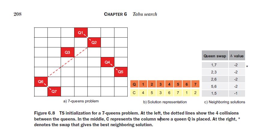
The n-queens problem is a classic puzzle that involves placing n chess queens on an n × n chessboard in such a way that no two queens threaten each other. In other words, no two queens should share the same row, column, or diagonal. This is a constraintsatisfaction problem (CSP) that does not define an explicit objective function. Let’s suppose we are attempting to solve a 7-queens problem using tabu search. In this problem, the number of collisions in the initial random configuration shown in figure 6.8a is 4: {Q1– Q2}, {Q2– Q6}, {Q4– Q5}, and {Q6– Q7}.
The above is part of the book Optimization Algorithms by Alaa Khamis, which I have used as a stepstone, in order to make a YT video, explaining the core of the tabu search with the algorithm. The solution of the n-queens problem is actually interesting, as its idea is to swap queen’s columns until these are allowed to be swaped and until the constrains are solved. The “tabu tenure” is just a type of record, that does not allow a certain change to be carried for a number of moves after it has been carried out. E.g., once you replace the columns of 2 queens, you are not allowed to do the same for the next 3 moves. This allows you to avoid loops.