Learn how to use Feature Flags in ASP.NET Core apps and read values from Azure App Configuration. Understand how to use filters, like the Percentage filter, to control feature activation, and learn how to take full control of the cache expiration of the values.
Table of Contents
Just a second! 🫷 If you are here, it means that you are a software developer.
So, you know that storage, networking, and domain management have a cost .
If you want to support this blog, please ensure that you have disabled the adblocker for this site. I configured Google AdSense to show as few ADS as possible – I don’t want to bother you with lots of ads, but I still need to add some to pay for the resources for my site.
Thank you for your understanding. – Davide
Feature Flags let you remotely control the activation of features without code changes. They help you to test, release, and manage features safely and quickly by driving changes using centralized configurations.
In this article, we are going to join the two streams in a single article: in fact, we will learn how to manage Feature Flags using Azure App Configuration to centralize our configurations.
It’s a sort of evolution from the previous article. Instead of changing the static configurations and redeploying the whole application, we are going to move the Feature Flags to Azure so that you can enable or disable those flags in just one click.
A recap of Feature Flags read from the appsettings file
Let’s reuse the example shown in the previous article.
We have an ASP.NET Core application (in that case, we were building a Razor application, but it’s not important for the sake of this article), with some configurations defined in the appsettings file under the Feature key:
Now we have to configure the same keys defined in the appsettings file: Header, Footer, and PrivacyPage.
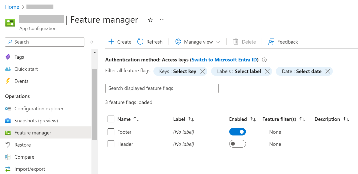
Open the App Configuration instance and locate the “Feature Manager” menu item in the left panel. This is the central place for creating, removing, and managing your Feature Flags. Here, you can see that I have already added the Header and Footer, and you can see their current state: “Footer” is enabled, while “Header” is not.
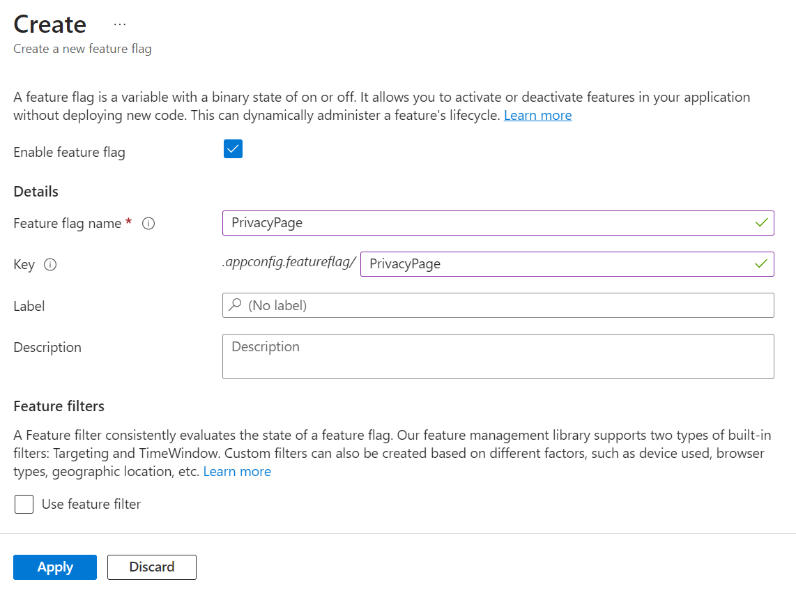
How can I add the PrivacyPage flag? It’s elementary: click the “Create” button and fill in the fields.
You have to define a Name and a Key (they can also be different), and if you want, you can add a Label and a Description. You can also define whether the flag should be active by checking the “Enable feature flag” checkbox.
Read Feature Flags from Azure App Configuration in an ASP.NET Core application
It’s time to integrate Azure App Configuration with our ASP.NET Core application.
Before moving to the code, we have to locate the connection string and store it somewhere.
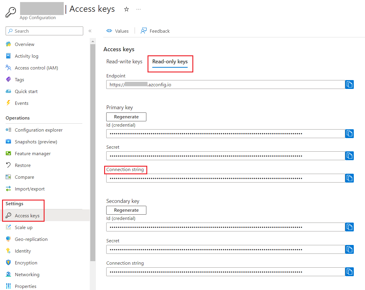
Head back to the App Configuration resource and locate the “Access keys” menu item under the “Settings” section.
From here, copy the connection string (I suggest that you use the Read-only Keys) and store it somewhere.
Before proceeding, you have to install the Microsoft.Azure.AppConfiguration.AspNetCore NuGet package.
Now, we can add Azure App Configuration as a source for our configurations by connecting to the connection string and by declaring that we are going to use Feature Flags:
Finally, once we have built our application with the usual builder.Build(), we have to add the Azure App Configuration middleware:
app.UseAzureAppConfiguration();
To try it out, run the application and validate that the flags are being applied. You can enable or disable those flags on Azure, restart the application, and check that the changes to the flags are being applied. Otherwise, you can wait 30 seconds to have the flag values refreshed and see the changes applied to your application.
Using the Percentage filter on Azure App Configuration
Suppose you want to enable a functionality only to a percentage of sessions (sessions, not users!). In that case, you can use the Percentage filter.
The previous article had a specific section dedicated to the PercentageFilter, so you might want to check it out.
Clearly, we can define such flags on Azure as well.
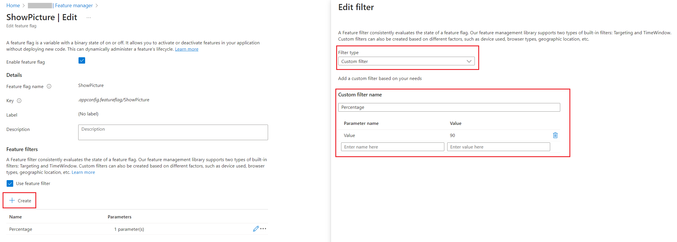
Head back to the Azure Portal and add a new Feature Flag. This time, you have to add a new Feature Filter to any existing flag. Even though the PercentageFilter is out-of-the-box in the FeatureManagement NuGet package, it is not available on the Azure portal.
You have to define the filter with the following values:
Filter Type must be “Custom”;
Custom filter name must be “Percentage”
You must add a new key, “Value”, and set its value to “60”.
The configuration we just added reflects the JSON value we previously had in the appsettings file: 60% of the requests will activate the flag, while the remaining 40% will not.
Define the cache expiration interval for Feature Flags
By default, Feature Flags are stored in an internal cache for 30 seconds.
Sometimes, it’s not the best choice for your project; you may prefer a longer duration to avoid additional calls to the App Configuration platform; other times, you’d like to have the changes immediately available.
You can then define the cache expiration interval you need by configuring the options for the Feature Flags:
This way, Feature Flag values are stored in the internal cache for 10 seconds. Then, when you reload the page, the configurations are reread from Azure App Configuration and the flags are applied with the new values.
Further readings
This is the final article of a path I built during these months to explore how to use configurations in ASP.NET Core.
We started by learning how to set configuration values in an ASP.NET Core application, as explained here:
Just a second! 🫷 If you are here, it means that you are a software developer.
So, you know that storage, networking, and domain management have a cost .
If you want to support this blog, please ensure that you have disabled the adblocker for this site. I configured Google AdSense to show as few ADS as possible – I don’t want to bother you with lots of ads, but I still need to add some to pay for the resources for my site.
Thank you for your understanding. – Davide
Model validation is fundamental to any project: it brings security and robustness acting as a first shield against an invalid state.
You should then add Unit Tests focused on model validation. In fact, when defining the input model, you should always consider both the valid and, even more, the invalid models, making sure that all the invalid models are rejected.
BDD is a good approach for this scenario, and you can use TDD to implement it gradually.
Okay, but how can you validate that the models and model attributes you defined are correct?
Have we defined our model correctly? Are we covering all the edge cases? A well-written Unit Test suite is our best friend here!
We have two choices: we can write Integration Tests to send requests to our system, which is running an in-memory server, and check the response we receive. Or we can use the internal Validator class, the one used by ASP.NET to validate input models, to create slim and fast Unit Tests. Let’s use the second approach.
Here’s a utility method we can use in our tests:
publicstatic IList<ValidationResult> ValidateModel(object model)
{
var results = new List<ValidationResult>();
var validationContext = new ValidationContext(model, null, null);
Validator.TryValidateObject(model, validationContext, results, true);
if (model is IValidatableObject validatableModel)
results.AddRange(validatableModel.Validate(validationContext));
return results;
}
In short, we create a validation context without any external dependency, focused only on the input model: new ValidationContext(model, null, null).
Next, we validate each field by calling TryValidateObject and store the validation results in a list, result.
Finally, if the Model implements the IValidatableObject interface, which exposes the Validate method, we call that Validate() method and store the returned validation errors in the final result list created before.
As you can see, we can handle both validation coming from attributes on the fields, such as [Required], and custom validation defined in the model class’s Validate() method.
Now, we can use this method to verify whether the validation passes and, in case it fails, which errors are returned:
[Test]publicvoid User_ShouldPassValidation_WhenModelIsValid()
{
var model = new User { FirstName = "Davide", LastName = "Bellone", Age = 32 };
var validationResult = ModelValidationHelper.ValidateModel(mode);
Assert.That(validationResult, Is.Empty);
}
[Test]publicvoid User_ShouldNotPassValidation_WhenLastNameIsEmpty()
{
var model = new User { FirstName = "Davide", LastName = null, Age = 32 };
var validationResult = ModelValidationHelper.ValidateModel(mode);
Assert.That(validationResult, Is.Not.Empty);
}
[Test]publicvoid User_ShouldNotPassValidation_WhenAgeIsLessThan18()
{
var model = new User { FirstName = "Davide", LastName = "Bellone", Age = 10 };
var validationResult = ModelValidationHelper.ValidateModel(mode);
Assert.That(validationResult, Is.Not.Empty);
}
Further readings
Model Validation allows you to create more robust APIs. To improve robustness, you can follow Postel’s law:
Model validation, in my opinion, is one of the cases where Unit Tests are way better than Integration Tests. This is a perfect example of Testing Diamond, the best (in most cases) way to structure a test suite:
If you still prefer writing Integration Tests for this kind of operation, you can rely on the WebApplicationFactory class and use it in your NUnit tests:
Learn how to integrate Oh My Posh, a cross-platform tool that lets you create beautiful and informative prompts for PowerShell.
Table of Contents
Just a second! 🫷 If you are here, it means that you are a software developer.
So, you know that storage, networking, and domain management have a cost .
If you want to support this blog, please ensure that you have disabled the adblocker for this site. I configured Google AdSense to show as few ADS as possible – I don’t want to bother you with lots of ads, but I still need to add some to pay for the resources for my site.
Thank you for your understanding. – Davide
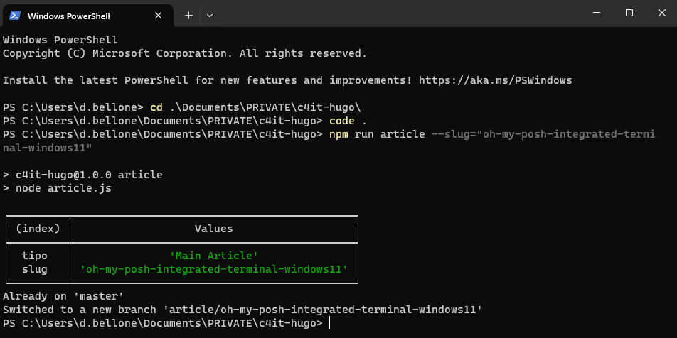
The content of the blog you are reading right now is stored in a Git repository. Every time I create an article, I create a new Git Branch to isolate the changes.
To generate the skeleton of the articles, I use the command line (well, I generally use PowerShell); in particular, given that I’m using both Windows 10 and Windows 11 – depending on the laptop I’m working on – I use the Integrated Terminal, which allows you to define the style, the fonts, and so on of every terminal configured in the settings.
The default profile is pretty basic: no info is shown except for the current path – I want to customize the appearance.
I want to show the status of the Git repository, including:
repository name
branch name
outgoing commits
There are lots of articles that teach how to use OhMyPosh with Cascadia Code. Unfortunately, I couldn’t make them work.
In this article, I teach you how I fixed it on my local machine. It’s a step-by-step guide I wrote while installing it on my local machine. I hope it works for you as well!
Step 1: Create the $PROFILE file if it does not exist
In PowerShell, you can customize the current execution by updating the $PROFILE file.
Clearly, you first have to check if the profile file exists.
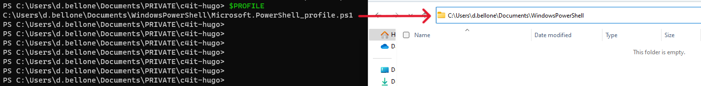
Open the PowerShell and type:
$PROFILE # You can also use $profile lowercase - it's the same!
This command shows you the expected path of this file. The file, if it exists, is stored in that location.
In this case, the $Profile file should be available under the folder C:\Users\d.bellone\Documents\WindowsPowerShell. In my case, it does not exist, though!
Therefore, you must create it manually: head to that folder and create a file named Microsoft.PowerShell_profile.ps1.
Note: it might happen that not even the WindowsPowerShell folder exists. If it’s missing, well, create it!
Step 2: Install OhMyPosh using Winget, Scoop, or PowerShell
To use OhMyPosh, we have to – of course – install it.
As explained in the official documentation, we have three ways to install OhMyPosh, depending on the tool you prefer.
And, if you like working with PowerShell, execute:
Set-ExecutionPolicy Bypass -Scope Process -Force; Invoke-Expression ((New-Object System.Net.WebClient).DownloadString('https://ohmyposh.dev/install.ps1'))
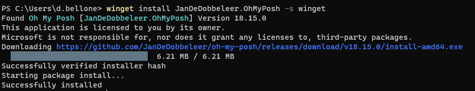
I used Winget, and you can see the installation process here:
Now, to apply these changes, you have to restart the PowerShell.
Step 3: Add OhMyPosh to the PowerShell profile
Open the Microsoft.PowerShell_profile.ps1 file and add the following line:
oh-my-posh init pwsh | Invoke-Expression
This command is executed every time you open the PowerShell with the default profile, and it initializes OhMyPosh to have it available during the current session.
Now, you can save and close the file.
Hint: you can open the profile file with Notepad by running notepad $PROFILE.
Step 4: Set the Execution Policy to RemoteSigned
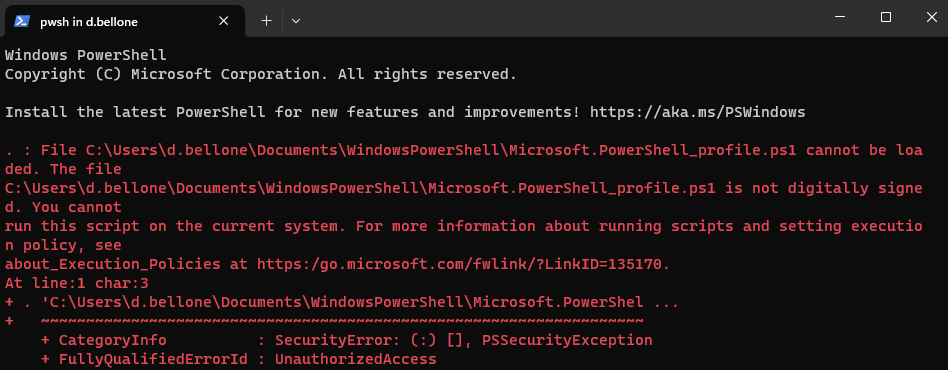
Restart the terminal. In all probability, you will see an error like this:
The error message
The file <path>\Microsoft.PowerShell_profile.ps1 is
not digitally signed. You cannot run this script on the current system
means that PowerShell does not trust the script it’s trying to load.
To see which Execution Policy is currently active, run:
You’ll probably see that the value is AllSigned.
To enable the execution of scripts created on your local machine, you have to set the Execution Policy value to RemoteSigned, using this command by running the PowerShell in administrator mode:
Set-ExecutionPolicy RemoteSigned
Let’s see the definition of the RemoteSigned Execution policy as per SQLShack’s article:
This is also a safe PowerShell Execution policy to set in an enterprise environment. This policy dictates that any script that was not created on the system that the script is running on, should be signed. Therefore, this will allow you to write your own script and execute it.
So, yeah, feel free to proceed and set the new Execution policy to have your PowerShell profile loaded correctly every time you open a new PowerShell instance.
Now, OhMyPosh can run in the current profile.
Head to a Git repository and notice that… It’s not working!🤬 Or, well, we have the Git information, but we are missing some icons and glyphs.
Step 5: Use CaskaydiaCove, not Cascadia Code, as a font
We still have to install the correct font with the missing icons.
We will install it using Chocolatey, a package manager available for Windows 11.
To check if you have it installed, run:
Now, to install the correct font family, open a PowerShell with administration privileges and run:
choco install cascadia-code-nerd-font
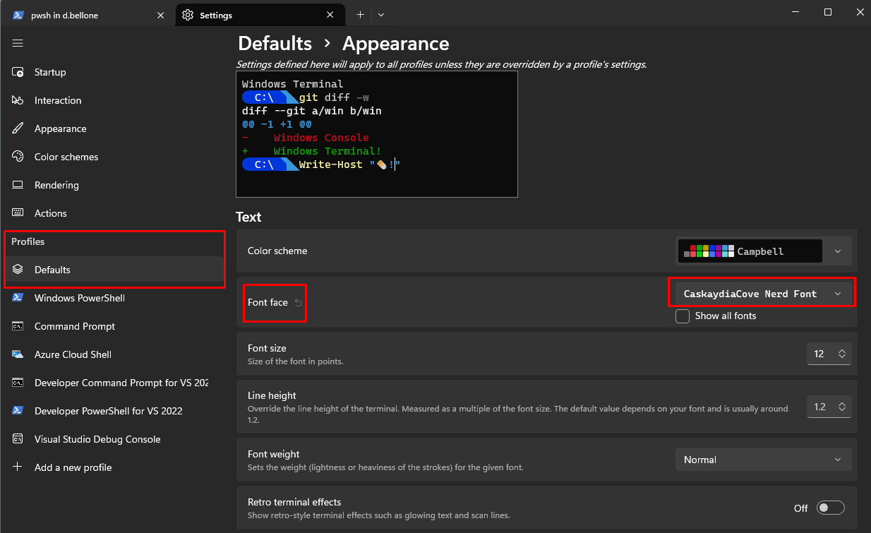
Once the installation is complete, you must tell Integrated Terminal to use the correct font by following these steps:
open to the Settings page (by hitting CTRL + ,)
select the profile you want to update (in my case, I’ll update the default profile)
open the Appearance section
under Font faceselect CaskaydiaCove Nerd Font
Now close the Integrated Terminal to apply the changes.
Open it again, navigate to a Git repository, and admire the result.
Further readings
The first time I read about OhMyPosh, it was on Scott Hanselman’s blog. I couldn’t make his solution work – and that’s the reason I wrote this article. However, in his article, he shows how he customized his own Terminal with more glyphs and icons, so you should give it a read.
We customized our PowerShell profile with just one simple configuration. However, you can do a lot more. You can read Ruud’s in-depth article about PowerShell profiles.
Finally, as I said at the beginning of this article, I use Git and Git Branches to handle the creation and management of my blog articles. That’s just the tip of the iceberg! 🏔️
If you want to steal my (previous) workflow, have a look at the behind-the-scenes of my blogging process (note: in the meanwhile, a lot of things have changed, but these steps can still be helpful for you)
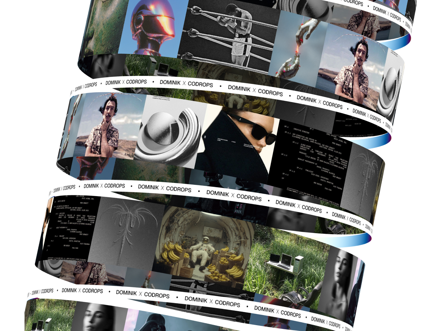
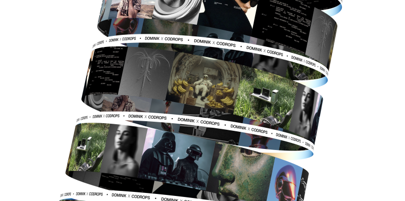
For the past few months, I’ve been exploring different kinetic motion designs with text and images. The style looks very intriguing, so I decided to create some really cool organic animations using images and React Three Fiber.
In this article, we’ll learn how to create the following animation using Canvas2D and React Three Fiber.
Setting Up the View & Camera
The camera’s field of view (FOV) plays a huge role in this project. Let’s keep it very low so it looks like an orthographic camera. You can experiment with different perspectives later. I prefer using a perspective camera over an orthographic one because we can always try different FOVs. For more detailed implementation check source code.
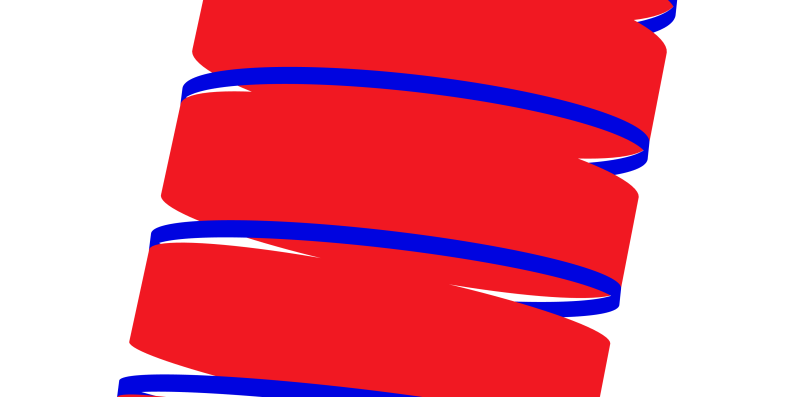
4. Add some rotation – Let’s rotate things a bit! First, I’ll hard-code the rotation of our banners to make them more curved and fit nicely with the Billboard component. We’ll also make the radius a bit bigger.
page.jsx
'use client';

import styles from './page.module.scss';
import Billboard from '@/components/webgl/Billboard/Billboard';
import Banner from '@/components/webgl/Banner/Banner';
import { View } from '@/webgl/View';
import { PerspectiveCamera } from '@react-three/drei';

const COUNT = 10;
const GAP = 3.2;

export default function Home() {
    return (
        <div className={styles.page}>
            <View className={styles.view} orbit={false}>
            <PerspectiveCamera makeDefault fov={7} position={[0, 0, 70]} near={0.01} far={100000} />
                <group>
                    {Array.from({ length: COUNT }).map((_, index) => [
                        <Billboard
                        key={`billboard-${index}`}
                        radius={5}
                        position={[0, (index - (Math.ceil(COUNT / 2) - 1)) * GAP, 0]}
                        rotation={[0, index * Math.PI * 0.5, 0]} // <-- rotation of the billboard
                        />,
                        <Banner
                        key={`banner-${index}`}
                        radius={5}
                        rotation={[0, 0, 0.085]} // <-- rotation of the banner
                        position={[0, (index - (Math.ceil(COUNT / 2) - 1)) * GAP - GAP * 0.5, 0]}
                        />,
                    ])}
                </group>
            </View>
        </div>
    );
}
5. Tilt the whole thing – Now let’s rotate our entire group to make it look like the Leaning Tower of Pisa.
page.jsx
'use client';

import styles from './page.module.scss';
import Billboard from '@/components/webgl/Billboard/Billboard';
import Banner from '@/components/webgl/Banner/Banner';
import { View } from '@/webgl/View';
import { PerspectiveCamera } from '@react-three/drei';

const COUNT = 10;
const GAP = 3.2;

export default function Home() {
    return (
        <div className={styles.page}>
            <View className={styles.view} orbit={false}>
            <PerspectiveCamera makeDefault fov={7} position={[0, 0, 70]} near={0.01} far={100000} />
                <group rotation={[-0.15, 0, -0.2]}> // <-- rotate the group
                    {Array.from({ length: COUNT }).map((_, index) => [
                        <Billboard
                        key={`billboard-${index}`}
                        radius={5}
                        position={[0, (index - (Math.ceil(COUNT / 2) - 1)) * GAP, 0]}
                        rotation={[0, index * Math.PI * 0.5, 0]}
                        />,
                        <Banner
                        key={`banner-${index}`}
                        radius={5}
                        rotation={[0, 0, 0.085]}
                        position={[0, (index - (Math.ceil(COUNT / 2) - 1)) * GAP - GAP * 0.5, 0]}
                        />,
                    ])}
                </group>
            </View>
        </div>
    );
}
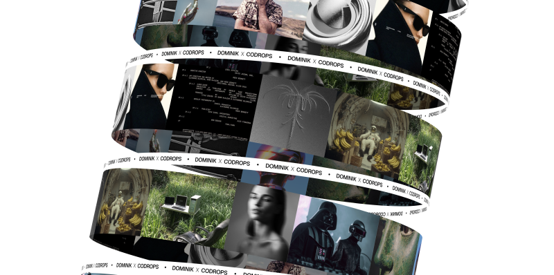
6. Perfect! – Our 3D shapes are all set up. Now we can add our images to them.
Creating a Texture from Our Images Using Canvas
Here’s the cool part: we’ll put all our images onto a canvas, then use that canvas as a texture on our Billboard shape.
To make this easier, I created some helper functions that simplify the whole process.
getCanvasTexture.js
import * as THREE from 'three';

/**
* Preloads an image and calculates its dimensions
*/
async function preloadImage(imageUrl, axis, canvasHeight, canvasWidth) {
    const img = new Image();

    img.crossOrigin = 'anonymous';

    await new Promise((resolve, reject) => {
        img.onload = () => resolve();
        img.onerror = () => reject(new Error(`Failed to load image: ${imageUrl}`));
        img.src = imageUrl;
    });

    const aspectRatio = img.naturalWidth / img.naturalHeight;

    let calculatedWidth;
    let calculatedHeight;

    if (axis === 'x') {
        // Horizontal layout: scale to fit canvasHeight
        calculatedHeight = canvasHeight;
        calculatedWidth = canvasHeight * aspectRatio;
        } else {
        // Vertical layout: scale to fit canvasWidth
        calculatedWidth = canvasWidth;
        calculatedHeight = canvasWidth / aspectRatio;
    }

    return { img, width: calculatedWidth, height: calculatedHeight };
}

function calculateCanvasDimensions(imageData, axis, gap, canvasHeight, canvasWidth) {
    if (axis === 'x') {
        const totalWidth = imageData.reduce(
        (sum, data, index) => sum + data.width + (index > 0 ? gap : 0), 0);

        return { totalWidth, totalHeight: canvasHeight };
    } else {
        const totalHeight = imageData.reduce(
        (sum, data, index) => sum + data.height + (index > 0 ? gap : 0), 0);

        return { totalWidth: canvasWidth, totalHeight };
    }
}

function setupCanvas(canvasElement, context, dimensions) {
    const { totalWidth, totalHeight } = dimensions;
    const devicePixelRatio = Math.min(window.devicePixelRatio || 1, 2);

    canvasElement.width = totalWidth * devicePixelRatio;
    canvasElement.height = totalHeight * devicePixelRatio;

    if (devicePixelRatio !== 1) context.scale(devicePixelRatio, devicePixelRatio);

    context.fillStyle = '#ffffff';
    context.fillRect(0, 0, totalWidth, totalHeight);
}

function drawImages(context, imageData, axis, gap) {
    let currentX = 0;
    let currentY = 0;

    context.save();

    for (const data of imageData) {
        context.drawImage(data.img, currentX, currentY, data.width, data.height);

        if (axis === 'x') currentX += data.width + gap;
        else currentY += data.height + gap;
    }

    context.restore();
}

function createTextureResult(canvasElement, dimensions) {
    const texture = new THREE.CanvasTexture(canvasElement);
    texture.needsUpdate = true;
    texture.wrapS = THREE.RepeatWrapping;
    texture.wrapT = THREE.ClampToEdgeWrapping;
    texture.generateMipmaps = false;
    texture.minFilter = THREE.LinearFilter;
    texture.magFilter = THREE.LinearFilter;

    return {
        texture,
        dimensions: {
            width: dimensions.totalWidth,
            height: dimensions.totalHeight,
            aspectRatio: dimensions.totalWidth / dimensions.totalHeight,
        },
    };
}

export async function getCanvasTexture({
    images,
    gap = 10,
    canvasHeight = 512,
    canvasWidth = 512,
    canvas,
    ctx,
    axis = 'x',
}) {
    if (!images.length) throw new Error('No images');

    // Create canvas and context if not provided
    const canvasElement = canvas || document.createElement('canvas');
    const context = ctx || canvasElement.getContext('2d');

    if (!context) throw new Error('No context');

    // Preload all images in parallel
    const imageData = await Promise.all(
        images.map((image) => preloadImage(image.url, axis, canvasHeight, canvasWidth))
    );

    // Calculate total canvas dimensions
    const dimensions = calculateCanvasDimensions(imageData, axis, gap, canvasHeight, canvasWidth);

    // Setup canvas
    setupCanvas(canvasElement, context, dimensions);

    // Draw all images
    drawImages(context, imageData, axis, gap);

    // Create and return texture result
    return createTextureResult(canvasElement, dimensions)
}
Then we can also create a useCollageTexture hook that we can easily use in our components.
Now let’s use our useCollageTexture hook on our page. We’ll create some simple loading logic. It takes a second to fetch all the images and put them onto the canvas. Then we’ll pass our texture and dimensions of canvas into the Billboard component.
page.jsx
'use client';

import styles from './page.module.scss';
import Billboard from '@/components/webgl/Billboard/Billboard';
import Banner from '@/components/webgl/Banner/Banner';
import Loader from '@/components/ui/modules/Loader/Loader';
import images from '@/data/images';
import { View } from '@/webgl/View';
import { PerspectiveCamera } from '@react-three/drei';
import { useCollageTexture } from '@/hooks/useCollageTexture';

const COUNT = 10;
const GAP = 3.2;

export default function Home() {
    const { texture, dimensions, isLoading } = useCollageTexture(images); // <-- getting the texture and dimensions from the useCollageTexture hook

    if (isLoading) return <Loader />; // <-- showing the loader when the texture is loading

    return (
        <div className={styles.page}>
            <View className={styles.view} orbit={false}>
                <PerspectiveCamera makeDefault fov={7} position={[0, 0, 100]} near={0.01} far={100000} />
                <group rotation={[-0.15, 0, -0.2]}>
                    {Array.from({ length: COUNT }).map((_, index) => [
                        <Billboard
                            key={`billboard-${index}`}
                            radius={5}
                            rotation={[0, index * Math.PI * 0.5, 0]}
                            position={[0, (index - (Math.ceil(COUNT / 2) - 1)) * GAP, 0]}
                            texture={texture} // <--passing the texture to the billboard
                            dimensions={dimensions} // <--passing the dimensions to the billboard
                        />,
                        <Banner
                            key={`banner-${index}`}
                            radius={5.035}
                            rotation={[0, 0, 0.085]}
                            position={[
                                0,
                                (index - (Math.ceil(COUNT / 2) - 1)) * GAP - GAP * 0.5,
                                0,
                            ]}
                        />,
                    ])}
                </group>
            </View>
        </div>
    );
}
Inside the Billboard component, we need to properly map this texture to make sure everything fits correctly. The width of our canvas will match the circumference of the cylinder, and we’ll center the y position of the texture. This way, all the images keep their resolution and don’t get squished or stretched.
Now let’s animate them using the useFrame hook. The trick to animating these images is to just move the X offset of the texture. This gives us the effect of a rotating mesh, when really we’re just moving the texture offset.
I think it would look even better if we made the back of the images a little darker. To do this, I created MeshImageMaterial – it’s just an extension of MeshBasicMaterial that makes our backface a bit darker.
MeshImageMaterial.js
import * as THREE from 'three';
import { extend } from '@react-three/fiber';

export class MeshImageMaterial extends THREE.MeshBasicMaterial {
    constructor(parameters = {}) {
        super(parameters);
        this.setValues(parameters);
    }

    onBeforeCompile = (shader) => {
        shader.fragmentShader = shader.fragmentShader.replace(
            '#include <color_fragment>',
            /* glsl */ `#include <color_fragment>
            if (!gl_FrontFacing) {
            vec3 blackCol = vec3(0.0);
            diffuseColor.rgb = mix(diffuseColor.rgb, blackCol, 0.7);
            }
            `
        );
    };
}

extend({ MeshImageMaterial });
And now we have our images moving around cylinders. Next, we’ll focus on banners (or marquees, whatever you prefer).
Adding Texture to the Banner
The last thing we need to fix is our Banner component. I wrapped it with this texture. Feel free to take it and edit it however you want, but remember to keep the proper dimensions of the texture.
We simply import our texture using the useTexture hook, map it onto our material, and animate the texture offset just like we did in our Billboard component.
Billboard.jsx
'use client';

import * as THREE from 'three';
import bannerTexture from '@/assets/images/banner.jpg';
import { useTexture } from '@react-three/drei';
import { useFrame } from '@react-three/fiber';
import { useRef } from 'react';

function Banner({ radius = 1.6, ...props }) {
    const ref = useRef(null);

    const texture = useTexture(bannerTexture.src);
    texture.wrapS = texture.wrapT = THREE.RepeatWrapping;

    useFrame((state, delta) => {
        if (!ref.current) return;
        const material = ref.current.material;
        if (material.map) material.map.offset.x += delta / 30;
    });

    return (
        <mesh ref={ref} {...props}>
            <cylinderGeometry
                args={[radius, radius, radius * 0.07, radius * 80, radius * 10, true]}
            />
            <meshBasicMaterial
                map={texture}
                map-anisotropy={16}
                map-repeat={[15, 1]}
                side={THREE.DoubleSide}
                toneMapped={false}
                backfaceRepeatX={3}
            />
        </mesh>
    );
}

export default Banner;
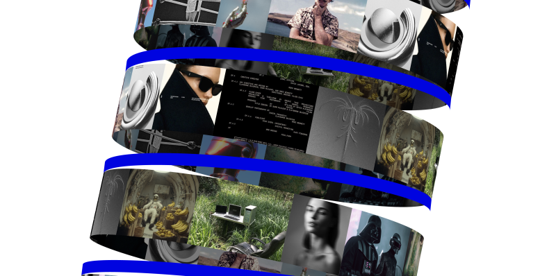
Nice! Now we have something cool, but I think it would look even cooler if we replaced the backface with something different. Maybe a gradient? For this, I created another extension of MeshBasicMaterial called MeshBannerMaterial. As you probably guessed, we just put a gradient on the backface. That’s it! Let’s use it in our Banner component.
We replace the MeshBasicMaterial with MeshBannerMaterial and now it looks like this!
MeshBannerMaterial.js
import * as THREE from 'three';
import { extend } from '@react-three/fiber';

export class MeshBannerMaterial extends THREE.MeshBasicMaterial {
    constructor(parameters = {}) {
        super(parameters);
        this.setValues(parameters);

        this.backfaceRepeatX = 1.0;

        if (parameters.backfaceRepeatX !== undefined)

        this.backfaceRepeatX = parameters.backfaceRepeatX;
    }

    onBeforeCompile = (shader) => {
        shader.uniforms.repeatX = { value: this.backfaceRepeatX * 0.1 };
        shader.fragmentShader = shader.fragmentShader
        .replace(
            '#include <common>',
            /* glsl */ `#include <common>
            uniform float repeatX;

            vec3 pal( in float t, in vec3 a, in vec3 b, in vec3 c, in vec3 d ) {
                return a + b*cos( 6.28318*(c*t+d) );
            }
            `
        )
        .replace(
            '#include <color_fragment>',
            /* glsl */ `#include <color_fragment>
            if (!gl_FrontFacing) {
            diffuseColor.rgb = pal(vMapUv.x * repeatX, vec3(0.5,0.5,0.5),vec3(0.5,0.5,0.5),vec3(1.0,1.0,1.0),vec3(0.0,0.10,0.20) );
            }
            `
        );
    };
}

extend({ MeshBannerMaterial });
Banner.jsx
'use client';

import * as THREE from 'three';
import bannerTexture from '@/assets/images/banner.jpg';
import { useTexture } from '@react-three/drei';
import { useFrame } from '@react-three/fiber';
import { useRef } from 'react';
import '@/webgl/materials/MeshBannerMaterial';

function Banner({ radius = 1.6, ...props }) {
const ref = useRef(null);

const texture = useTexture(bannerTexture.src);

texture.wrapS = texture.wrapT = THREE.RepeatWrapping;

useFrame((state, delta) => {
    if (!ref.current) return;

    const material = ref.current.material;

    if (material.map) material.map.offset.x += delta / 30;
});

return (
    <mesh ref={ref} {...props}>
        <cylinderGeometry
            args={[radius, radius, radius * 0.07, radius * 80, radius * 10, true]}
        />
        <meshBannerMaterial
            map={texture}
            map-anisotropy={16}
            map-repeat={[15, 1]}
            side={THREE.DoubleSide}
            toneMapped={false}
            backfaceRepeatX={3}
        />
    </mesh>
);
}

export default Banner;
You can experiment with this method in lots of ways. For example, I created 2 more examples with shapes I made in Blender, and mapped canvas textures on them. You can check them out here:
Final Words
Check out the final versions of all demos:
I hope you enjoyed this tutorial and learned something new!
Feel free to check out the source code for more details!
In today’s world, organizations are rapidly embracing cloud security to safeguard their data and operations. However, as cloud adoption grows, so do the risks. In this post, we highlight the top cloud security challenges and show how Seqrite can help you tackle them with ease.
1. Misconfigurations
One of the simplest yet most dangerous mistakes is misconfiguring cloud workloads think storage buckets left public, weak IAM settings, or missing encryption. Cybercriminals actively scan for these mistakes. A small misconfiguration can lead to significant data leakage or worst-case, ransomware deployment. Seqrite Endpoint Protection Cloud ensure your cloud environment adheres to best-practice security settings before threats even strike.
2. Shared Responsibility Confusion
The cloud model operates on shared responsibility: providers secure infrastructure, you manage your data and configurations. Too many teams skip this second part. Inadequate control over access, authentication, and setup drives serious risks. With Seqrite’s unified dashboard for access control, IAM, and policy enforcement, you stay firmly in control without getting overwhelmed.
3. Expanded Attack Surface
More cloud services, more code, more APIs, more opportunities for attacks. Whether it’s serverless functions or public API endpoints, the number of access points grows quickly. Seqrite tackles this with integrated API scanning, vulnerability assessment, and real-time threat detection. Every service, even ephemeral ones is continuously monitored.
4. Unauthorized Access & Account Hijacking
Attackers often gain entry via stolen credentials, especially in shared or multi-cloud environments. Once inside, they move laterally and hijack more resources. Seqrite’s multi-factor authentication, adaptive risk scoring, and real-time anomaly detection lock out illicit access and alert you instantly.
5. Insufficient Data Encryption
Unencrypted data whether at rest or in transit is a gold mine for attackers. Industries with sensitive or regulated information, like healthcare or finance, simply can’t afford this. Seqrite ensures enterprise-grade encryption everywhere you store or transmit data and handles key management so that it’s secure and hassle-free.
6. Poor Visibility and Monitoring
Without centralized visibility, security teams rely on manual cloud consoles and piecemeal logs. That slows response and leaves gaps. Seqrite solves this with a unified monitoring layer that aggregates logs and events across all your cloud environments. You get complete oversight and lightning-fast detection.
7. Regulatory Compliance Pressures
Compliance with GDPR, HIPAA, PCI-DSS, DPDPA and other regulations is mandatory—but complex in multi-cloud environments. Seqrite Data Privacy simplifies compliance with continuous audits, policy enforcement, and detailed reports, helping you reduce audit stress and regulatory risk.
8. Staffing & Skills Gap
Hiring cloud-native, security-savvy experts is tough. Many teams lack the expertise to monitor and secure dynamic cloud environments. Seqrite’s intuitive interface, automation, and policy templates remove much of the manual work, allowing lean IT teams to punch above their weight.
9. Multi-cloud Management Challenges
Working across AWS, Azure, Google Cloud and maybe even private clouds? Each has its own models and configurations. This fragmentation creates blind spots and policy drift. Seqrite consolidates everything into one seamless dashboard, ensuring consistent cloud security policies across all environments.
10. Compliance in Hybrid & Multi-cloud Setups
Hybrid cloud setups introduce additional risks, cross-environment data flows, networking complexities, and inconsistent controls. Seqrite supports consistent security policy application across on-premises, private clouds, and public clouds, no matter where a workload lives.
Bring in Seqrite to secure your cloud journey, safe, compliant, and hassle-free.
Learn how to zip and unzip compressed files with C#. Beware: it’s not as obvious as it might seem!
Table of Contents
Just a second! 🫷 If you are here, it means that you are a software developer.
So, you know that storage, networking, and domain management have a cost .
If you want to support this blog, please ensure that you have disabled the adblocker for this site. I configured Google AdSense to show as few ADS as possible – I don’t want to bother you with lots of ads, but I still need to add some to pay for the resources for my site.
Thank you for your understanding. – Davide
When working with local files, you might need to open, create, or update Zip files.
In this article, we will learn how to work with Zip files in C#. We will learn how to perform basic operations such as opening, extracting, and creating a Zip file.
The main class we will use is named ZipFile, and comes from the System.IO.Compression namespace. It’s been present in C# since .NET Framework 4.5, so we can say it’s pretty stable 😉 Nevertheless, there are some tricky points that you need to know before using this class. Let’s learn!
Using C# to list all items in a Zip file
Once you have a Zip file, you can access the internal items without extracting the whole Zip.
You can use the ZipFile.Open method.
using ZipArchive archive = ZipFile.Open(zipFilePath, ZipArchiveMode.Read);
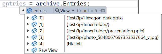
System.Collections.ObjectModel.ReadOnlyCollection<ZipArchiveEntry> entries = archive.Entries;
Notice that I specified the ZipArchiveMode. This is an Enum whose values are Read, Create, and Update.
Using the Entries property of the ZipArchive, you can access the whole list of files stored within the Zip folder, each represented by a ZipArchiveEntry instance.
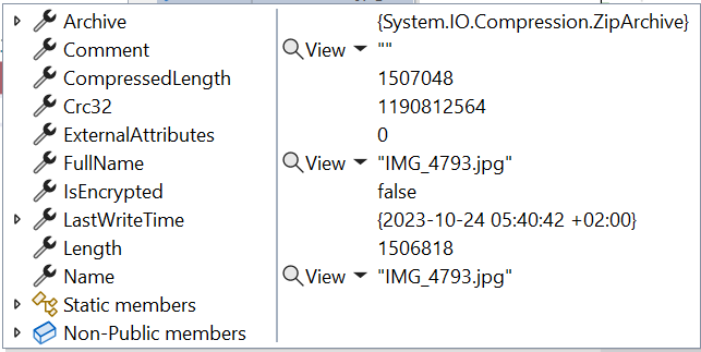
The ZipArchiveEntry object contains several fields, like the file’s name and the full path from the root archive.
There are a few key points to remember about the entries listed in the ZipArchiveEntry.
It is a ReadOnlyCollection<ZipArchiveEntry>: it means that even if you find a way to add or update the items in memory, the changes are not applied to the actual files;
It lists all files and folders, not only those at the root level. As you can see from the image above, it lists both the files at the root level, like File.txt, and those in inner folders, such as TestZip/InnerFolder/presentation.pptx;
Each file is characterized by two similar but different properties: Name is the actual file name (like presentation.pptx), while FullName contains the path from the root of the archive (e.g. TestZip/InnerFolder/presentation.pptx);
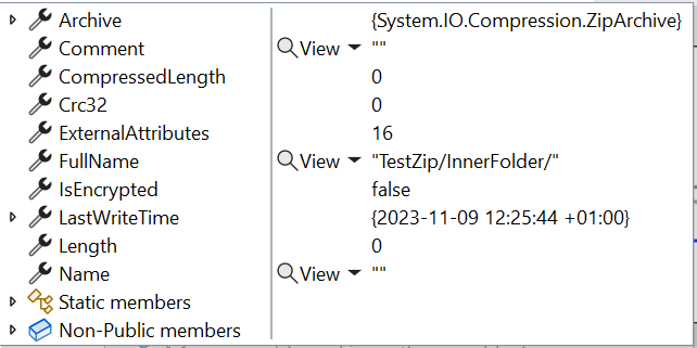
It lists folders as if they were files: in the image above, you can see TestZip/InnerFolder. You can recognize them because their Name property is empty and their Length is 0;
Lastly, remember that ZipFile.Open returns an IDisposable, so you should place the operations within a using statement.
❓❓A question for you! Why do we see an item for the TestZip/InnerFolder folder, but there is no reference to the TestZip folder? Drop a comment below 📩
Extracting a Zip folder is easy but not obvious.
We have only one way to do that: by calling the ZipFile.ExtractToDirectory method.
It accepts as mandatory parameters the path of the Zip file to be extracted and the path to the destination:
var zipPath = @"C:\Users\d.bellone\Desktop\TestZip.zip";
var destinationPath = @"C:\Users\d.bellone\Desktop\MyDestination";
ZipFile.ExtractToDirectory(zipPath, destinationPath);
Once you run it, you will see the content of the Zip copied and extracted to the MyDestination folder.
Note that this method creates the destination folder if it does not exist.
This method accepts two more parameters:
entryNameEncoding, by which you can specify the encoding. The default value is UTF-8.
overwriteFiles allows you to specify whether it must overwrite existing files. The default value is false. If set to false and the destination files already exist, this method throws a System.IO.IOException saying that the file already exists.
Using C# to create a Zip from a folder
The key method here is ZipFile.CreateFromDirectory, which allows you to create Zip files in a flexible way.
The first mandatory value is, of course, the source directory path.
The second mandatory parameter is the destination of the resulting Zip file.
Or it can be a Stream that you can use later for other operations:
using (MemoryStream memStream = new MemoryStream())
{
string sourceFolderPath = @"\Desktop\myFolder";
ZipFile.CreateFromDirectory(sourceFolderPath, memStream);
var lenght = memStream.Length;// here the Stream is populated}
You can finally add some optional parameters:
compressionLevel, whose values are Optimal, Fastest, NoCompression, SmallestSize.
includeBaseDirectory: a flag that defines if you have to copy only the first-level files or also the root folder.
A quick comparison of the four Compression Levels
As we just saw, we have four compression levels: Optimal, Fastest, NoCompression, and SmallestSize.
What happens if I use the different values to zip all the photos and videos of my latest trip?
Fastest compression generates a smaller file than Smallest compression.
Fastest compression is way slower than Smallest compression.
Optimal lies in the middle.
This is to say: don’t trust the names; remember to benchmark the parts where you need performance, even with a test as simple as this.
Wrapping up
This was a quick article about one specific class in the .NET ecosystem.
As we saw, even though the class is simple and it’s all about three methods, there are some things you should keep in mind before using this class in your code.
I hope you enjoyed this article! Let’s keep in touch on Twitter or LinkedIn! 🤜🤛
Fragment shaders allow us to create smooth, organic visuals that are difficult to achieve with standard polygon-based rendering in WebGL. One powerful example is the metaball effect, where multiple objects blend and deform seamlessly. This can be implemented using a technique called ray marching, directly within a fragment shader.
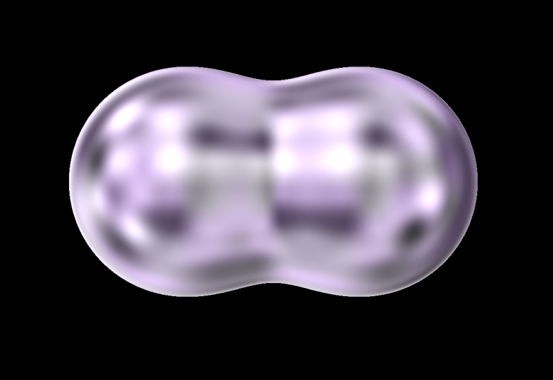
In this tutorial, we’ll walk you through how to create droplet-like, bubble spheres using Three.js and GLSL—an effect that responds interactively to your mouse movements. But first, take a look at the demo video below to see the final result in action.
Overview
Let’s take a look at the overall structure of the demo and review the steps we’ll follow to build it.
We arrange spheres along the mouse trail to create a stretchy, elastic motion.
Let’s get started!
1. Setup
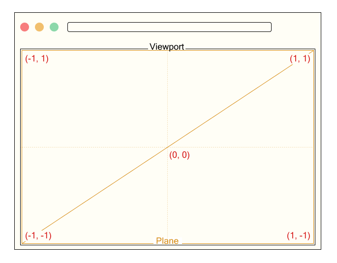
We render a single fullscreen plane that covers the entire viewport.
// Output.ts

const planeGeometry = new THREE.PlaneGeometry(2.0, 2.0);
const planeMaterial = new THREE.RawShaderMaterial({
    vertexShader: base_vert,
    fragmentShader: output_frag,
    uniforms: this.uniforms,
});
const plane = new THREE.Mesh(planeGeometry, planeMaterial);
this.scene.add(plane);
We define a uniform variable named uResolution to pass the canvas size to the shader, where Common.width and Common.height represent the width and height of the canvas in pixels. This uniform will be used to normalize coordinates based on the screen resolution.
The vertex shader receives the position attribute.
Since the xy components of position originally range from -1 to 1, we convert them to a range from 0 to 1 and output them as a texture coordinate called vTexCoord. This is passed to the fragment shader and used to calculate colors or effects based on the position on the screen.
The fragment shader receives the interpolated texture coordinate vTexCoord and the uniform variable uResolution representing the canvas size. Here, we temporarily use vTexCoord to output color for testing.
Now we’re all set to start drawing in the fragment shader! Next, let’s move on to actually rendering the spheres.
2. Ray Marching
2.1. What is Ray Marching?
As mentioned at the beginning, we will use a method called ray marching to render spheres. Ray marching proceeds in the following steps:
Define the scene
Set the camera (viewing) direction
Cast rays
Evaluate the distance from the current ray position to the nearest object in the scene.
Move the ray forward by that distance
Check for a hit
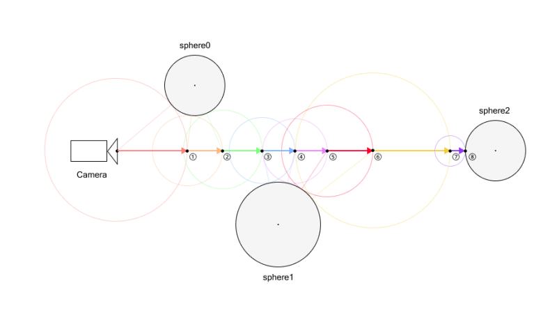
For example, let’s consider a scene with three spheres. These spheres are expressed using SDFs (Signed Distance Functions), which will be explained in detail later.
First, we determine the camera direction. Once the direction is set, we cast a ray in that direction.
Next, we evaluate the distance to all objects from the current ray position, and take the minimum of these distances.
After obtaining this distance, we move the ray forward by that amount.
We repeat this process until either the ray gets close enough to an object—closer than a small threshold—or the maximum number of steps is reached. If the distance is below the threshold, we consider it a “hit” and shade the corresponding pixel.
For example, in the figure above, a hit is detected on the 8th ray marching step.
If the maximum number of steps were set to 7, the 7th step would not have hit anything yet. But since the limit is reached, the loop ends and no hit is detected.
Therefore, nothing would be rendered at that position. If parts of an object appear to be missing in the final image, it may be due to an insufficient number of steps. However, be aware that increasing the step count will also increase the computational load.
To better understand this process, try running this demo to see how it works in practice.
2.2. Signed Distance Function
In the previous section, we briefly mentioned the SDF (Signed Distance Function). Let’s take a moment to understand what it is.
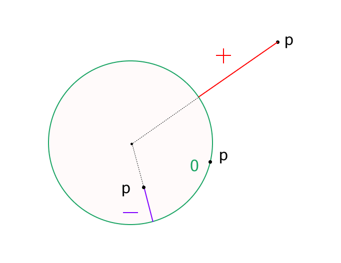
An SDF is a function that returns the distance from a point to a particular shape. The key characteristic is that it returns a positive or negative value depending on whether the point is outside or inside the shape.
For example, here is the distance function for a sphere:
Here, p is a vector representing the position relative to the origin, and s is the radius of the sphere.
This function calculates how far the point p is from the surface of a sphere centered at the origin with radius s.
If the result is positive, the point is outside the sphere.
If negative, it is inside the sphere.
If the result is zero, the point is on the surface—this is considered a hit point (in practice, we detect a hit when the distance is less than a small threshold).
In this demo, we use a sphere’s distance function, but many other shapes have their own distance functions as well.
After that, inside the map function, two spheres are defined and their distances calculated using sdSphere. The variable d is initially set to a large value and updated with the min function to keep track of the shortest distance to the surface.
Then we run a ray marching loop, which updates the ray position by computing the distance to the nearest object at each step. The loop ends either after a fixed number of iterations or when the distance becomes smaller than a threshold (dist < EPS):
for ( int i = 0; i < ITR; ++ i ) {
	dist = map(ray);
	ray += rayDirection * dist;
	if ( dist < EPS ) break ;
}
Finally, we determine the output color. We use black as the default color (background), and render a white pixel only if a hit is detected:
vec3 color = vec3(0.0);

if ( dist < EPS ) {
	color = vec3(1.0);
}
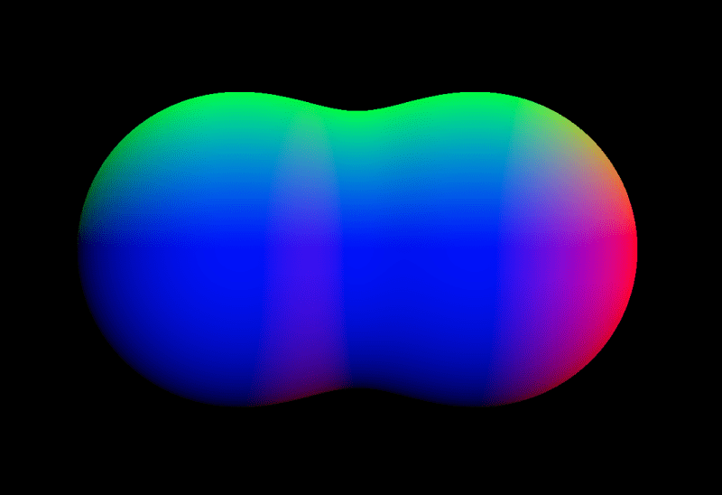
We’ve successfully rendered two overlapping spheres using ray marching!
2.4. Normals
Although we successfully rendered spheres in the previous section, the scene still looks flat and lacks depth. This is because we haven’t applied any shading or visual effects that respond to surface orientation.
While we won’t implement full shading in this demo, we’ll still compute surface normals, as they’re essential for adding surface detail and other visual effects.
At first glance, this may seem hard to understand. Put simply, this computes the gradient of the distance function, which corresponds to the normal vector.
If you’ve studied vector calculus, this might be easy to understand. For many others, though, it may seem a bit difficult.
However, for those who are interested in how it works, we’ll now walk through the explanation in more detail.
The gradient of a scalar function 𝑓(𝑥,𝑦,𝑧) is simply a vector composed of its partial derivatives. It points in the direction of the greatest rate of increase of the function:
To compute this gradient numerically, we can use the central difference method. For example:
We apply the same idea for the 𝑦 and 𝑧 components. Note: The factor 2𝜀 is omitted in the code since we normalize the result using normalize().
Next, let us consider a signed distance function 𝑓(𝑥,𝑦,𝑧), which returns the shortest distance from any point in space to the surface of an object. By definition, 𝑓(𝑥,𝑦,𝑧)=0 on the surface of the object.
Assume that 𝑓 is smooth (i.e., differentiable) in the region of interest. When the point (𝑥,𝑦,𝑧) undergoes a small displacement Δ𝒓=(Δ𝑥,Δ𝑦,Δ𝑧), the change in the function value Δ𝑓 can be approximated using the first-order Taylor expansion:
Here,∇𝑓 is the gradient vector of 𝑓, and Δ𝒓 is an arbitrary small displacement vector.
Now, since 𝑓=0 on the surface and remains constant as we move along the surface (i.e., tangentially), the function value does not change, so Δ𝑓=0. Therefore:
This means that the gradient vector is perpendicular to any tangent vector Δ𝒓 on the surface. In other words, the gradient vector ∇𝑓 points in the direction of the surface normal.
Thus, the gradient of a signed distance function gives the surface normal direction at any point on the surface.
2.5. Visualizing Normals with Color
To verify that the surface normals are being calculated correctly, we can visualize them using color.
if ( dist < EPS ) {
	vec3 normal = generateNormal(ray);
	color = normal;
}
Note that within the if block, ray refers to a point on the surface of the object. So by passing ray to generateNormal, we can obtain the surface normal at the point of intersection.
When we render the scene, you’ll notice that the surface of the sphere is shaded in red, green, and blue based on the orientation of the normal vectors. This is because we’re mapping the 𝑥, 𝑦, and 𝑧 components of the normal vector to the RGB color channels respectively.
This is a common and intuitive way to debug normal vectors visually, helping us ensure they are computed correctly.
When combining two spheres with the standard min() function, a hard edge forms where the shapes intersect, resulting in an unnatural boundary. To avoid this, we can use a blending function called smoothMin, which softens the transition by merging the distance values smoothly.
This function creates a smooth, continuous connection between shapes—producing a metaball-like effect where the forms appear to merge organically.
The parameter k controls the smoothness of the blend. A higher k value results in a sharper transition (closer to min()), while a lower k produces smoother, more gradual merging.
For more details, please refer to the following two articles:
So far, we’ve covered how to calculate normals and how to smoothly blend objects.
Next, let’s tune the surface appearance to make things feel more realistic.
In this demo, we’re aiming to create droplet-like metaballs. So how can we achieve that kind of look? The key idea here is to use noise to distort the surface.
To create the droplet-like texture, we’re using value noise. If you’re unfamiliar with these noise techniques, the following articles provide helpful explanations:
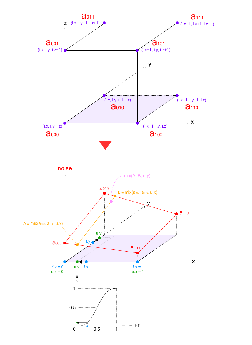
3D value noise is generated by interpolating random values placed at the eight vertices of a cube. The process involves three stages of linear interpolation:
Bottom face interpolation: First, we interpolate between the four corner values on the bottom face of the cube
Top face interpolation: Similarly, we interpolate between the four corner values on the top face
Final z-axis interpolation: Finally, we interpolate between the results from the bottom and top faces along the z-axis
This triple interpolation process is called trilinear interpolation.
The following code demonstrates the trilinear interpolation process for 3D value noise:
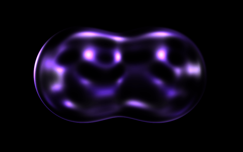
By sampling this noise using the reflection vector as coordinates, we can create a realistic water droplet-like texture. Note that we are using the surface normal obtained earlier to compute this reflection vector. To add time-based variation, we generate noise at positions offset by uTime:
It’s starting to look quite like a water droplet! However, it still appears a bit murky. To improve this, let’s add the following post-processing step:
In today’s hyper-connected digital world, the cybersecurity landscape is shifting dramatically. Gone are the days when cyberattacks primarily relied on human intervention. We’re now facing a new breed of silent, swift adversaries: non-human threats. These automated entities—bots, malicious scripts, and sophisticated malware—are designed to operate at machine speed, exploiting vulnerabilities, bypassing traditional defenses, and often remaining undetected until significant damage has occurred. So, how do you defend against something you can’t see, something that moves faster than human reaction? The answer lies in intelligent, automated endpoint security. Enter Seqrite Endpoint Protection (EPP), your robust shield against these invisible invaders. Available for both cloud-based and on-premise deployments, Seqrite EPP is engineered with cutting-edge technologies specifically designed to identify and neutralize these stealthy, non-human threats.
Understanding the Enigma: What Exactly Are Non-Human Cyber Threats?
When we talk about “non-human cyber threats,” we’re referring to automated programs and code snippets that launch attacks without requiring direct human interaction. These include:
Bots: Automated programs designed to perform repetitive tasks at scale. Think credential stuffing attacks where bots try thousands of username/password combinations, or Distributed Denial of Service (DDoS) attacks that flood a server with traffic.
Malicious Scripts: These are pieces of automated code, often hidden within legitimate-looking files or web pages, designed to exploit system weaknesses, exfiltrate sensitive data, or spread malware across your network.
Exploit Kits: These are sophisticated toolkits that automatically scan systems for unpatched vulnerabilities and then deploy exploits to gain unauthorized access or deliver payloads like ransomware.
The key characteristic of these threats is their autonomy and speed. They operate under the radar, making traditional, reactive security measures largely ineffective. This is precisely why proactive, automated detection and prevention mechanisms are absolutely critical for modern businesses.
Seqrite Endpoint Protection: Your Multi-Layered Defense Against Automation
Seqrite’s EPP doesn’t just offer a single line of defense; it deploys a comprehensive, multi-layered security framework. This framework is specifically engineered to detect and block automation-driven threats using a powerful combination of intelligent rule-based systems, behavioral analysis, and advanced AI-powered capabilities.
Let’s dive into the key features that make Seqrite EPP a formidable opponent against non-human threats:
Advanced Device Control: Many non-human threats, especially scripts and certain types of malware, are delivered via external devices like USB drives. Seqrite’s Advanced Device Control enforces strict usage policies, allowing you to define what devices can connect to your endpoints and how they can be used. By controlling storage, network, and wireless interfaces, you effectively close off a major entry point for automated attacks.
Application Control with Zero Trust: Imagine only allowing approved applications and scripts to run on your systems. That’s the power of Seqrite’s Application Control. By implementing a Zero Trust model, it blocks unknown or unapproved applications and scripts from executing. Through meticulous allowlisting and blocklisting, only trusted applications can operate, making it incredibly effective against stealthy automation tools that attempt to execute malicious code.
Behavior-Based Detection (GoDeep.AI): This is where Seqrite truly shines. Leveraging cutting-edge AI and machine learning, GoDeep.AI continuously monitors endpoint activity to identify abnormal and suspicious behaviors that indicate a non-human threat. This includes detecting:
Repetitive access patterns: A hallmark of bots attempting to brute-force accounts or scan for vulnerabilities.
Scripted encryption behavior: Instantly flags the tell-tale signs of ransomware encrypting files.
Silent data exfiltration attempts: Catches automated processes trying to siphon off sensitive information. The system doesn’t just detect; it actively stops suspicious activity in its tracks before it can cause any harm.
Intrusion Detection & Prevention System (IDS/IPS): Seqrite’s integrated IDS/IPS actively monitors network traffic for known exploit patterns and anomalous behavior. This robust system is crucial for blocking automation-based threats that attempt to infiltrate your network through known vulnerabilities or launch network-based attacks like port scanning.
File Sandboxing: When a suspicious file or script enters your environment, Seqrite doesn’t let it run directly on your system. Instead, it’s whisked away to a secure, isolated virtual sandbox environment for deep analysis. Here, the file is allowed to execute and its behavior is meticulously observed. If it exhibits any malicious traits—like attempting to mimic user behavior, access restricted resources, or encrypt files—it’s immediately flagged and stopped, preventing any potential damage to your actual endpoints.
Web Protection & Phishing Control: Many non-human threats, particularly bots and sophisticated malware, rely on communication with remote command-and-control (C2) servers. Seqrite’s Web Protection proactively blocks:
Access to known malicious domains.
Phishing sites designed to steal credentials.
Unauthorized web access that could lead to malware downloads.
Crucially, it cuts off botnet callbacks, effectively severing the communication lines between bots and their command centers, rendering them inert.
Enhancing Your Defense: Essential Supporting Features
Beyond its core capabilities, Seqrite Endpoint Protection is bolstered by a suite of supporting features that further strengthen your organization’s resilience against non-human threats and beyond:
Feature
Benefit
Patch Management
Automatically identifies and fixes software vulnerabilities that bots and scripts often exploit to gain entry. Proactive patching is key to prevention.
Firewall
Provides a critical layer of defense by filtering unauthorized network traffic and blocking communication with known botnet IP addresses.
Data Loss Prevention (DLP)
Prevents automated data theft by monitoring and controlling data in transit, ensuring sensitive information doesn’t leave your network without authorization.
Centralized Log Management
Offers a unified view of security events, allowing for rapid detection and auditing of unusual or suspicious behaviors across all endpoints.
Disk Encryption Management
Safeguards your data by encrypting entire disks, stopping automated decryption attempts even if data is stolen, and protecting against ransomware.
The Future of Endpoint Security: Why Non-Human Threat Detection is Non-Negotiable
As we move deeper into 2025 and beyond, cyber threats are becoming increasingly automated, sophisticated, and often, AI-driven. Relying on traditional, signature-based security solutions is no longer enough to match the speed, stealth, and evolving tactics of automation-based attacks.
Seqrite Endpoint Protection is built for this future. It leverages intelligent automation to effectively combat automation—blocking bots, malicious scripts, advanced ransomware, and other non-human threats before they can execute and wreak havoc on your systems and data.
Final Takeaway: Don’t Let Invisible Threats Compromise Your Business
In a world where cyberattacks are increasingly executed by machines, your defense must be equally advanced. With its comprehensive suite of features—including cutting-edge device and application control, AI-driven behavioral detection (GoDeep.AI), robust network-level protection, and secure sandboxing—Seqrite Endpoint Protection ensures your endpoints remain locked down and secure.
Whether your organization operates with a cloud-first strategy or relies on a traditional on-premise infrastructure, Seqrite provides the adaptable and powerful security solutions you need.
Ready to Fortify Your Defenses?
It’s time to upgrade your endpoint security and protect your organization from both human-initiated and the ever-growing wave of non-human cyber threats.