برچسب: The

  • Invisible Forces: The Making of Phantom.land’s Interactive Grid and 3D Face Particle System

    Invisible Forces: The Making of Phantom.land’s Interactive Grid and 3D Face Particle System


    From the outset, we knew we wanted something that subverted any conventional agency website formulas. Instead,
    inspired by the unseen energy that drives creativity, connection and transformation, we arrived at the idea of
    invisible forces
    . Could we take the powerful yet intangible elements that shape our world—motion, emotion, intuition, and
    inspiration—and manifest them in a digital space?

    We were excited about creating something that included many custom interactions and a very experiential feel. However,
    our concern was picking a set of tools that would allow most of our developers to contribute to and maintain the site
    after launch.

    We chose to start from a Next / React base, as we often do at Phantom. React also has the advantage of being
    compatible with the excellent React Three Fiber library, which we used to seamlessly bridge the gap between our DOM
    components and the WebGL contexts used across the site. For styles, we are using our very own
    CSS components
    as well as SASS.

    For interactive behaviours and animation, we chose to use GSAP for two main reasons. Firstly, it contains a lot of
    plugins we know and love, such as SplitText, CustomEase and ScrollTrigger. Secondly, GSAP allows us to use a single
    animation framework across DOM and WebGL components.

    We could go on and on talking about the details behind every single animation and micro-interaction on the site, but
    for this piece we have chosen to focus our attention on two of the most unique components of our site: the homepage
    grid and the scrollable employee face particle carousel.
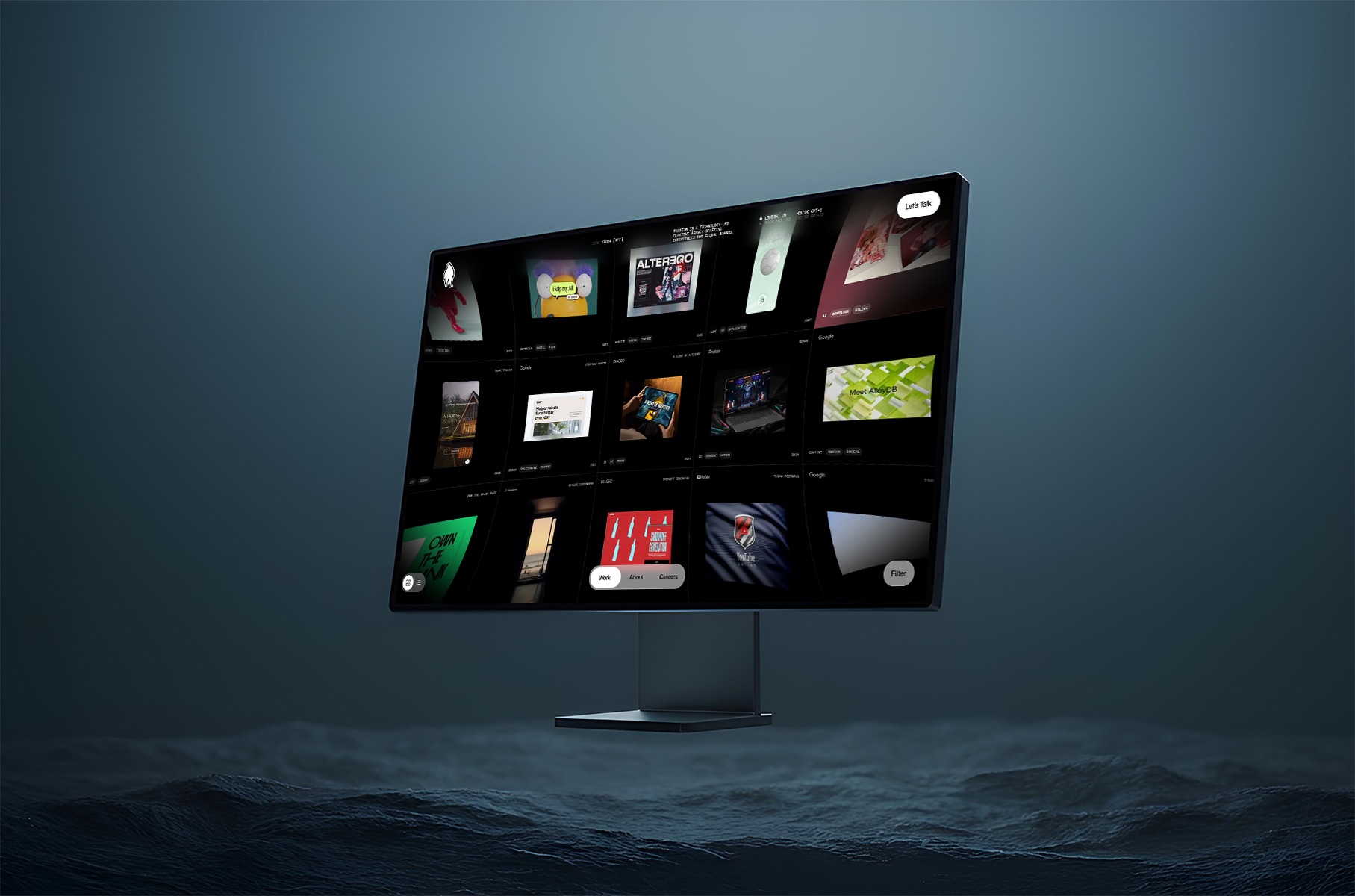
    The Homepage Grid

    It took us a very long time to get this view to perform and feel just how we wanted it to. In this article, we will focus on the interactive part. For more info on how we made things performant, head to our previous article: Welcome back to Phantomland

    Grid View

    The project’s grid view is integrated into the homepage by incorporating a primitive Three.js object into a React
    Three Fiber scene.

    //GridView.tsx
    const GridView = () => {
      return (
        <Canvas>
          ...
          <ProjectsGrid />
          <Postprocessing />
        </Canvas>
      );
    }
    
    //ProjectsGrid.tsx
    const ProjectsGrid = ({atlases, tiles}: Props) => {
      const {canvas, camera} = useThree();
      
      const grid = useMemo(() => {
        return new Grid(canvas, camera, atlases, tiles);
      }, [canvas, camera, atlases, tiles]);
    
      if(!grid) return null;
      return (
        <primitive object={grid} />
      );
    }

    We initially wanted to write all the code for the grid using React Three Fiber but realised that, due to the
    complexity of our grid component, a vanilla
    Three.js
    class would be easier to maintain.

    One of the key elements that gives our grid its iconic feel is our post-processing distortion effect. We implemented
    this feature by creating a custom shader pass within our post-processing pipeline:

    // Postprocessing.tsx
    const Postprocessing = () => {
      const {gl, scene, camera} = useThree();
      
      // Create Effect composer
      const {effectComposer, distortionShader} = useMemo(() => {
        const renderPass = new RenderPass(scene, camera);
        const distortionShader = new DistortionShader();
        const distortionPass = new ShaderPass(distortionShader);
        const outputPass = new OutputPass();
    
        const effectComposer = new EffectComposer(gl);
        effectComposer.addPass(renderPass);
        effectComposer.addPass(distortionPass);
        effectComposer.addPass(outputPass);
    
        return {effectComposer, distortionShader};
      }, []);
      
      // Update distortion intensity
      useEffect(() => {
        if (workgridState === WorkgridState.INTRO) {
          distortionShader.setDistortion(CONFIG.distortion.flat);
        } else {
          distortionShader.setDistortion(CONFIG.distortion.curved);
        }
      }, [workgridState, distortionShader]);
      
      // Update distortion intensity
      useFrame(() => {
        effectComposer.render();
      }, 1);
     
      return null;
    }

    When the grid transitions in and out on the site, the distortion intensity changes to make the transition feel
    natural. This animation is done through a simple tween in our
    DistortionShader
    class:

    class DistortionShader extends ShaderMaterial {
      private distortionIntensity = 0;
    
      super({
          name: 'DistortionShader',
          uniforms: {
            distortionIntensity: {value: new Vector2()},
            ...
          },
          vertexShader,
          fragmentShader,
      });
    
      update() {
        const ratio = window.innerWidth, window.innerHeight;
        this.uniforms[DistortionShaderUniforms.DISTORTION].value.set(
          this.distortionIntensity * ratio,
          this.distortionIntensity * ratio,
        );
      }
    
      setDistortion(value: number) {
        gsap.to(this, {
          distortionIntensity: value,
          duration: 1,
          ease: 'power2.out',
          onUpdate: () => this.update()    }
      }
    }

    Then the distortion is applied through our custom shader:

    // fragment.ts
    export const fragmentShader = /* glsl */ `
      uniform sampler2D tDiffuse;
      uniform vec2 distortion;
      uniform float vignetteOffset;
      uniform float vignetteDarkness;
    
      varying vec2 vUv;
      
      // convert uv range from 0 -> 1 to -1 -> 1
      vec2 getShiftedUv(vec2 uv) {
        return 2. * (uv - .5);
      }
      
      // convert uv range from -1 -> 1 to 0 -> 1
      vec2 getUnshiftedUv(vec2 shiftedUv) {
        return shiftedUv * 0.5 + 0.5;
      }
    
    
      void main() {
        vec2 shiftedUv = getShiftedUv(vUv);
        float distanceToCenter = length(shiftedUv);
        
        // Lens distortion effect
        shiftedUv *= (0.88 + distortion * dot(shiftedUv));
        vec2 transformedUv = getUnshiftedUv(shiftedUv);
        
        // Vignette effect
        float vignetteIntensity = smoothstep(0.8, vignetteOffset * 0.799,  (vignetteDarkness + vignetteOffset) * distanceToCenter);
        
        // Sample render texture and output fragment
        color = texture2D( tDiffuse, distortedUV ).rgb * vignetteIntensity;
        gl_FragColor = vec4(color, 1.);
      }

    We also added a vignette effect to our post-processing shader to darken the corners of the viewport, focusing the
    user’s attention toward the center of the screen.

    In order to make our home view as smooth as possible, we also spent a fair amount of time crafting the
    micro-interactions and transitions of the grid.

    Ambient mouse offset

    When the user moves their cursor around the grid, the grid moves slightly in the opposite direction, creating a very
    subtle ambient floating effect. This was simply achieved by calculating the mouse position on the grid and moving the
    grid mesh accordingly:

    getAmbientCursorOffset() {
      // Get the pointer coordinates in UV space ( 0 - 1 ) range
      const uv = this.navigation.pointerUv;
      const offset = uv.subScalar(0.5).multiplyScalar(0.2);
      return offset;
    }
    
    update() {
      ...
      // Apply cursor offset to grid position
      const cursorOffset = getAmbientCursorOffset();
      this.mesh.position.x += cursorOffset.x;
      this.mesh.position.y += cursorOffset.y;
    }

    Drag Zoom

    When the grid is dragged around, a zoom-out effect occurs and the camera seems to pan away from the grid. We created
    this effect by detecting when the user starts and stops dragging their cursor, then using that to trigger a GSAP
    animation with a custom ease for extra control.

    onPressStart = () => {
      this.animateCameraZ(0.5, 1);
    }
    
    onPressEnd = (isDrag: boolean) => {
      if(isDrag) {
        this.animateCameraZ(0, 1);
      }
    }
    
    animateCameraZ(distance: number, duration: number) {
      gsap.to(this.camera.position, {
        z: distance,
        duration,
        ease: CustomEase.create('cameraZoom', '.23,1,0.32,1'),
      });
    }

    Drag Movement

    Last but not least, when the user drags across the grid and releases their cursor, the grid slides through with a
    certain amount of inertia.

    drag(offset: Vector2) {
      this.dragAction = offset;
    
      // Gradually increase velocity with drag time and distance
      this.velocity.lerp(offset, 0.8);
    }
    
    // Every frame
    update() {
      // positionOffset is later used to move the grid mesh
      if(this.isDragAction) {
        // if the user is dragging their cursor, add the drag value to offset
        this.positionOffset.add(this.dragAction.clone());
      } else {
        // if the user is not dragging, add the velocity to the offset
        this.positionOffset.add(this.velocity);
      }
    
      this.dragAction.set(0, 0);
      // Attenuate velocity with time
      this.velocity.lerp(new Vector2(), 0.1);
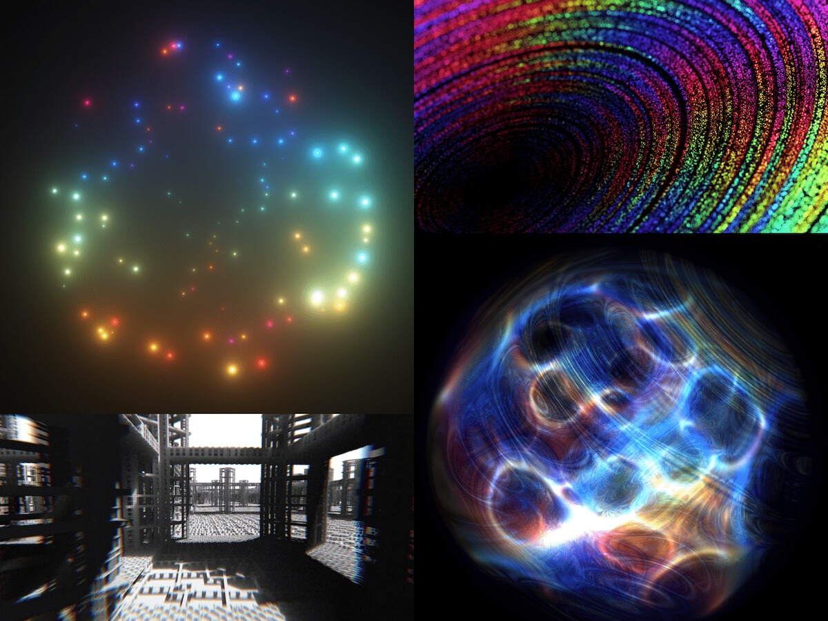
    }

    Face Particles

    The second major component we want to highlight is our employee face carousel, which presents team members through a
    dynamic 3D particle system. Built with React Three Fiber’s
    BufferGeometry
    and custom GLSL shaders, this implementation leverages custom shader materials for lightweight performance and
    flexibility, allowing us to generate entire 3D face representations using only a 2D colour photograph and its
    corresponding depth map—no 3D models required.

    Core Concept: Depth-Driven Particle Generation

    The foundation of our face particle system lies in converting 2D imagery into volumetric 3D representations. We’ve
    kept things efficient, with each face using only two optimized 256×256 WebP images (under 15KB each).

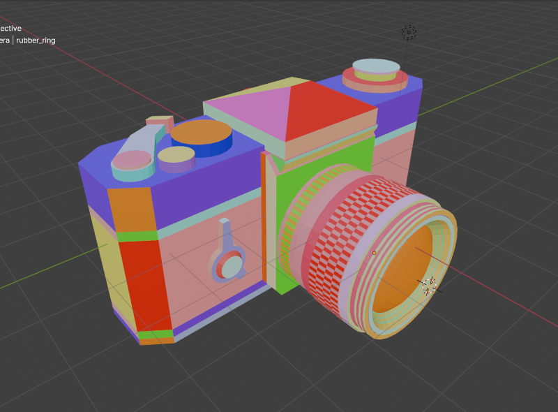
    To capture the images, each member of the Phantom team was 3D scanned using
    RealityScan
    from Unreal Engine on iPhone, creating a 3D model of their face.

    These scans were cleaned up and then rendered from Cinema4D with a position and colour pass.

    The position pass was converted into a greyscale depth map in Photoshop, and this—along with the colour pass—was
    retouched where needed, cropped, and then exported from Photoshop to share with the dev team.

    Each face is constructed from approximately 78,400 particles (280×280 grid), where each particle’s position and
    appearance is determined by sampling data from our two source textures.

    /* generate positions attributes array */
    const POINT_AMOUNT = 280;
    
    const points = useMemo(() => {
      const length = POINT_AMOUNT * POINT_AMOUNT;
      const vPositions = new Float32Array(length * 3);
      const vIndex = new Float32Array(length * 2);
      const vRandom = new Float32Array(length * 4);
    
      for (let i = 0; i < length; i++) {
          const i2 = i * 2;
          vIndex[i2] = (i % POINT_AMOUNT) / POINT_AMOUNT;
          vIndex[i2 + 1] = i / POINT_AMOUNT / POINT_AMOUNT;
    
          const i3 = i * 3;
          const theta = Math.random() * 360;
          const phi = Math.random() * 360;
          vPositions[i3] = 1 * Math.sin(theta) * Math.cos(phi);
          vPositions[i3 + 1] = 1 * Math.sin(theta) * Math.sin(phi);
          vPositions[i3 + 2] = 1 * Math.cos(theta);
    
          const i4 = i * 4;
          vRandom.set(
            Array(4)
              .fill(0)
              .map(() => Math.random()),
            i4,
          );
      }
    
      return {vPositions, vRandom, vIndex};
    }, []);
    // React Three Fiber component structure 
    const FaceParticleSystem = ({ particlesData, currentDataIndex }) => {
      return (
        <points ref={pointsRef} position={pointsPosition}>
          <bufferGeometry>
            <bufferAttribute attach="attributes-vIndex" 
                 args={[points.vIndex, 2]} />
            <bufferAttribute attach="attributes-position"
                 args={[points.vPositions, 3]} />
            <bufferAttribute attach="attributes-vRandom"
                 args={[points.vRandom, 4]} />
          </bufferGeometry>
          
          <shaderMaterial
            blending={NormalBlending}
            transparent={true}
            fragmentShader={faceFrag}
            vertexShader={faceVert}
            uniforms={uniforms}
          />
        </points>
      );
    };

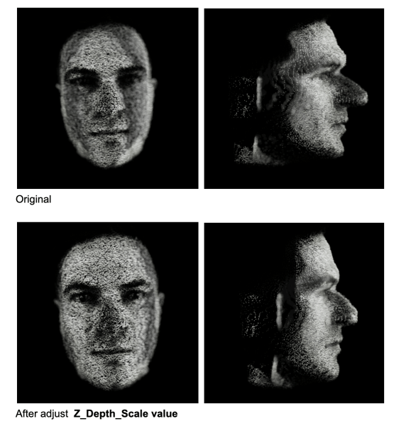
    The depth map provides normalized values (0–1) that directly translate to Z-depth positioning. A value of 0 represents
    the furthest point (background), while 1 represents the closest point (typically the nose tip).

    /* vertex shader */ 
    
    // sample depth and color data for each particle
    vec3 depthTexture1 = texture2D(depthMap1, vIndex.xy).xyz;
    
    // convert depth to Z-position
    float zDepth = (1. - depthValue.z);
    pos.z = (zDepth * 2.0 - 1.0) * zScale;

    Dynamic Particle Scaling Through Colour Analysis

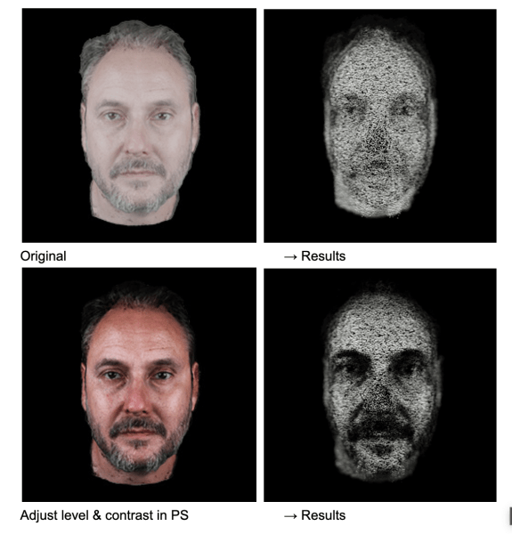
    One of the key methods that brings our faces to life is utilizing colour data to influence particle scale. In our
    vertex shader, rather than using uniform particle sizes, we analyze the colour density of each pixel so that brighter,
    more colourful areas of the face (like eyes, lips, or well-lit cheeks) generate larger, more prominent particles,
    while darker areas (shadows, hair) create smaller, subtler particles. The result is a more organic, lifelike
    representation that emphasizes facial features naturally.

    /* vertex shader */ 
    
    vec3 colorTexture1 = texture2D(colorMap1, vIndex.xy).xyz;
    
    // calculate color density
    float density = (mainColorTexture.x + mainColorTexture.y + mainColorTexture.z) / 3.;
    
    // map density to particle scale
    float pScale = mix(pScaleMin, pScaleMax, density);

    The calibration below demonstrates the influence of colour (contrast, brightness, etc.) on the final 3D particle formation.

    Ambient Noise Animation

    To prevent static appearances and maintain visual interest, we apply continuous noise-based animation to all
    particles. This ambient animation system uses curl noise to create subtle, flowing movement across the entire
    face structure.

    /* vertex shader */ 
    
    // primary curl noise for overall movement 
    pos += curlNoise(pos * curlFreq1 + time) * noiseScale * 0.1;
    // animation updates in React Three Fiber
    
    useFrame((state, delta) => {
      if (!materialRef.current) return;
      
      materialRef.current.uniforms.time.value = state.clock.elapsedTime * NOISE_SPEED;
      
      // update rotation based on mouse interaction
      easing.damp(pointsRef.current.rotation, 'y', state.mouse.x * 0.12 * Math.PI, 0.25, delta);
      easing.damp(pointsRef.current.rotation, 'x', -state.pointer.y * 0.05 * Math.PI, 0.25, delta);
    
    });

    Face Transition Animation

    When transitioning between different team members, we combine timeline-based interpolation with visual effects written
    in shader materials.

    GSAP-Driven Lerp Method

    The transition foundation uses GSAP timelines to animate multiple shader parameters simultaneously:

    timelineRef.current = gsap
      .timeline()
      .fromTo(uniforms.transition, {value: 0}, {value: 1.3, duration: 1.6})
      .to(uniforms.posZ, {value: particlesParams.offset_z, duration: 1.6}, 0)
      .to(uniforms.zScale, {value: particlesParams.face_scale_z, duration: 1.6}, 0);

    And the shader handles the visual blending between two face states:

    /* vertex shader */ 
    
    // smooth transition curve
    float speed = clamp(transition * mix(0.8, .9, transition), 0., 1.0); 
    speed = smoothstep(0.0, 1.0, speed); 
    
    // blend textures 
    vec3 mainColorTexture = mix(colorTexture1, colorTexture2, speed); 
    vec3 depthValue =mix(depthTexture1, depthTexture2, speed);

    To add visual interest during transitions, we further inject additional noise that’s strongest at the midpoint of the
    transition. This creates a subtle “disturbance” effect where particles temporarily deviate from their target
    positions, making transitions feel more dynamic and organic.

    /* vertex shader */ 
    
    // secondary noise movement applied for transition
    float randomZ = vRandom.y + cnoise(pos * curlFreq2 + t2) * noiseScale2;
    
    float smoothTransition = abs(sin(speed * PI)); 
    pos.x += nxScale * randomZ * 0.1 * smoothTransition; 
    pos.y += nyScale *randomZ * 0.1 * smoothTransition;
    pos.z += nzScale * randomZ * 0.1 * smoothTransition;

    Custom Depth of Field Effect

    To enhance the three-dimensional perception, we implemented a custom depth of field effect directly in our shader
    material. It calculates view-space distance for each particle and modulates both opacity and size based on proximity
    to a configurable focus plane.

    /* vertex shader - calculate view distance */
    
    vec4 viewPosition = viewMatrix * modelPosition;
    vDistance = abs(focus +viewPosition.z); 
    
    // apply distance to point size for blur effect 
    gl_PointSize = pointSize * pScale * vDistance * blur * totalScale;
    /* fragment shader - calculate distance-based alpha for DOF */
    
    
    float alpha = (1.04 - clamp(vDistance * 1.5, 0.0, 1.0));
    gl_FragColor = vec4(color, alpha);

    Challenges: Unifying Face Scales

    One of the challenges we faced was achieving visual consistency across different team members’ photos. Each photograph
    was captured under slightly different conditions—varying lighting, camera distances, and facial proportions.
    Therefore, we went through each face to calibrate multiple scaling factors:

    • Depth scale calibration
      to ensure no nose protrudes too aggressively
    • Colour density balancing
      to maintain consistent particle size relationships
    • Focus plane optimization
      to prevent excessive blur on any individual face
    // individual face parameters requiring manual tuning 
    
    particle_params: { 
      offset_z: 0,           // overall Z-position
      z_depth_scale: 0,      // depth map scaling factor
      face_size: 0,          // overall face scale 
    }

    Final Words

    Our face particle system demonstrates how simple yet careful technical implementation can create fun visual
    experiences from minimal assets. By combining lightweight WebP textures, custom shader materials, and animations,
    we’ve created a system that transforms simple 2D portraits into interactive 3D figures.

    Check out the full site.

    Curious about what we’re up to in the Phantom studio? Or have a project you think we’d be interested in? Get in touch.


    Source link

  • Inside the Frontier of AI, WebXR & Real-Time 3D: Crafting KODE Immersive

    Inside the Frontier of AI, WebXR & Real-Time 3D: Crafting KODE Immersive


    KODE Immersive fuses AR, VR, real-time 3D, and spatial computing to craft high-impact, interactive experiences. It’s not just a platform – it’s a portal. Designed to ignite emotion, shatter expectations, and redefine digital engagement.

    Our challenge? To bring this pioneering vision to life, not just by explaining what KODE Immersive is, but by making visitors experience what it’s like to be inside it.

    Background

    Our relationship with KODE began in 2022 when we extended their brand identity and reimagined their digital home. What started as a brand refresh quickly evolved into a creative partnership rooted in shared values and a mutual obsession with crafted brand experience and beautiful design.

    In late 2024, KODE approached us with a new venture. This time, they were diving headfirst into emerging technologies (AI, WebXR, and real-time 3D) to expand their service offering. We knew immediately, this was the kind of project you dream about. It was a timely opportunity and got us excited to push boundaries.

    The Brief

    The brief was as open as it gets. Beyond a few core objectives (namely, budget and timeline), there were no strict constraints. We received a three-slide deck: a name, a positioning statement, three brand pillars (CREATE, IDEATE, DELIVER), and a few straplines.

    No case studies. No visual identity. Just a bold vision.

    And that freedom became our greatest asset. We built everything from scratch, visual language, tone, interactions, while staying mindful of budget and speed. Our approach:  move fast, iterate often, and push boundaries.

    To pull it off, we adopted a phased R&D process. We teamed up with the brilliant Francesco Michelini (who previously helped build the Malvah website). Francesco lives and breathes WebGL. He once spent a week refining a mechanic we had already agreed to abandon, just because he couldn’t accept defeat. That kind of drive made him the perfect collaborator.

    Our Process

    We used KODE Immersive as a live testing ground for our refined four-phase process, aimed at delivering the best creative solutions while avoiding unnecessary feedback loops. Here’s how it shaped the final outcome.

    01 Discover

    We kicked things off with an in-depth strategy session where we unpacked the brief, explored concepts, discussed competitors, and mapped out technical possibilities. Style tiles helped form the foundation of our visual language.

    Typography was the key differentiator. We knew the right typeface would communicate innovation and intent. After multiple rounds, we landed on Brut by Off-Type – an unconventional mono-inspired form that struck just the right balance of structure and tension.

    Colour took cues from the parent brand, but we flipped the hierarchy. Orange became the dominant tone, with bold black moments layered throughout. Familiar, yet distinctive.

    Iconography evolved from KODE’s chevron mark. We repurposed it as a modular, dynamic system to guide interactions and reflect the brand’s three core pillars.

    02 Create

    This phase became interesting, since the experience would rely heavily on user interaction, this phase was driven more by prototyping than traditional design. We worked in tight, iterative loops with the client, across design, 3D, and development to test feasibility early and often. It became an it was extremely organic process and ideal to reach the deadline while stretching limitations.

    From the start, we knew we didn’t just want users to interact—we wanted them to feel immersed. To lose track of time by being emotionally and mentally engaged. 

    We developed a range of 3D concepts in Cinema 4D and funnelled them through R&D cycles. The process required a lot of iterating and relooking creative solutions, but was always collaborative – and ultimately, essential for innovation.

    03 Craft

    This is where the magic happens. 

    Our craft is what we consider our special sauce at Malvah – this is where we like to push, refine, and design with intent and clarity. It’s hard not to get lost in the sauce. Massive respect for Francesco during this phase as it is the most intense in terms of iterations, from shader logic to ambient lighting to the haptic quality of cursor interactions, and every component was built to feel immersive yet effortless. Luckily, Francesco is an actual living wizard and provided us with testing environments where we could craft all these elements seamlessly. 

    Still, something was missing! The high-fidelity 3D was clashing with the flat backgrounds. The fix? A subtle layer of pixel distortion and soft noise texture. Minimal, but transformative. Suddenly, the whole experience felt unified – like everything belonged as one unified, harmonious experience.

    04 Deliver

    By final QA, most of the heavy lifting was done. We stress-tested performance across browsers, devices, and connection speeds. We refined micro-interactions and polished details based on early user feedback.

    Tech Stack

    Nerd stuff alert.

    From the outset, this was always going to be a Three.js and WebGL project – not for the novelty, but for the storytelling power. Real-time 3D let us turn a static brand into a living, breathing experience. We used Cinema 4D for concepting and prototyping, from early ideation through to final modelling and meta-cap creation.

    One of the most impactful performance optimisations came through the use of BatchedMesh, which enabled us to draw multiple meshes sharing the same material in a single draw call. Since draw calls are among the most expensive operations in WebGL, this dramatically improved efficiency, reducing calls from 40 or 50 down to just one. You’ll see this in action in both the hero section and the footer, where we also implemented the Rapier physics engine for dynamic interaction.

    The real breakthrough, however, was moving the rendering of our most resource-intensive canvases to an OffscreenCanvas, with all related logic handled inside a WebWorker. This shift happened later in the project and required significant reworking, but the gains in performance and responsiveness were undeniable. It was a technically ambitious move, but one that paid off. 

    Features

    The site follows a continuous scroll narrative—a careful dance between interactivity, emotion, and information. With the primary goal to provoke curiosity and invite deep engagement, rom top to bottom, here’s a rundown of our favourite features.

    Chevron

    We land on the hero of the brand, the logo-mark. The chevron is the anchor,  both literally and metaphorically. The driving force behind the iconography that would funnel through the experience. We wanted the entry point to set the tone, bold, dynamic, and intuitive for the user to explore. 

    Shifting Text

    One of those happy accidents. Inspired by a line that didn’t make the final copy, we developed a mechanic where text splits and shifts as the cursor moves. A metaphor for deconstruction and reformation – fluid, dynamic, alive.

    Icons

    A playful space to explore, discover, and interact. Designed to echo the brand’s chevron and embody its core pillars.

    Menu

    One of our favourite elements. It subverts the typical UX pattern by growing from the base and transforming into the footer as users scroll; a small disruption that makes a big impact.

    SFX

    Sound is often the unsung hero. We follow the 80/20 rule here, also known as the Pareto Principle —just the right amount to amplify emotion without overwhelming the experience. From section transitions to hover feedback, the layered soundscape adds depth and atmosphere. The transition from the landing section to the services has the user feeling as if they are entering a new realm.

    We worked with Martin Leitner from Sounds Good to curate the sound elements in aiding the experience and bringing the interaction with the 3D elements to life. This was such a great experience, and Martin’s enthusiasm helped drive the process and the team’s excitement. 

    Easter Egg

    We always planned for an easter egg, we just didn’t know what it was until it revealed itself.

    A sketch mechanic, pulled from KODE’s visual identity, was integrated into the cursor. Users can draw on the screen to reveal a hidden layer; a playful nod to the analogue-digital duality of the brand.

    Early testers were missing it entirely. So we added a subtle auto-activation trigger at just the right moment. Problem solved.

    Reflections

    This project reminded us that the best results often emerge from ambiguity. No case studies. No visual assets. No roadmap. Just vision and trust.

    While we’re proud of what we’ve delivered, we’ve only scratched the surface. Phase Two will introduce interactive case studies and deeper storytelling. We’re especially excited to explore a z-axis scroll journey through each service, bringing dimension and discovery to the next level.For now, KODE Immersive is live.

    And it’s only getting started.


    Source link

  • Why Data Principal Rights Management Is the Heart of Modern Privacy Compliance|Seqrite

    Why Data Principal Rights Management Is the Heart of Modern Privacy Compliance|Seqrite


    As data privacy laws evolve globally—from the GDPR to India’s Digital Personal Data Protection Act (DPDPA)—one common theme emerges: empowering individuals with control over their data. This shift places data principal rights at the center of privacy compliance.

    Respecting these rights isn’t just a legal obligation for organizations; it’s a business imperative. Efficiently operationalizing and fulfilling data principal rights is now a cornerstone of modern privacy programs.

    Understanding Data Principal Rights

    Data principal rights refer to the entitlements granted to individuals regarding their data. Under laws like the DPDPA and GDPR, these typically include:

    • Right to Access: Individuals can request a copy of the personal data held about them.
    • Right to Correction: They can demand corrections to inaccurate or outdated data.
    • Right to Erasure (Right to Be Forgotten): They can request deletion of their data under specific circumstances.
    • Right to Data Portability: They can request their data in a machine-readable format.
    • Right to Withdraw Consent: They can withdraw previously given consent for data processing.
    • Right to Grievance Redressal: They can lodge complaints if their rights are not respected.

    While these rights sound straightforward, fulfilling them at scale is anything but simple, especially when data is scattered across cloud platforms, internal systems, and third-party applications.

    Why Data Principal Rights Management is Critical

    1. Regulatory Compliance and Avoidance of Penalties

    Non-compliance can result in substantial fines, regulatory scrutiny, and reputational harm. For instance, DPDPA empowers the Data Protection Board of India to impose heavy penalties for failure to honor data principal rights on time.

    1. Customer Trust and Transparency

    Respecting user rights builds transparency and demonstrates that your organization values privacy. This can increase customer loyalty and strengthen brand reputation in privacy-conscious markets.

    1. Operational Readiness and Risk Reduction

    Organizations risk delays, errors, and missed deadlines when rights requests are handled manually. An automated and structured rights management process reduces legal risk and improves operational agility.

    1. Auditability and Accountability

    Every action taken to fulfill a rights request must be logged and documented. This is essential for proving compliance during audits or investigations.

    The Role of Data Discovery in Rights Fulfilment

    To respond to any data principal request, you must first know where the relevant personal data resides. This is where Data Discovery plays a crucial supporting role.

    A robust data discovery framework enables organizations to:

    • Identify all systems and repositories that store personal data.
    • Correlate data to specific individuals or identifiers.
    • Retrieve, correct, delete, or port data accurately and quickly.

    Without comprehensive data visibility, any data principal rights management program will fail, resulting in delays, partial responses, or non-compliance.

    Key Challenges in Rights Management

    Despite its importance, many organizations struggle with implementing effective data principal rights management due to:

    • Fragmented data environments: Personal data is often stored in silos, making it challenging to aggregate and act upon.
    • Manual workflows: Fulfilling rights requests often involves slow, error-prone manual processes.
    • Authentication complexities: Verifying the identity of the data principal securely is essential to prevent abuse of rights.
    • Lack of audit trails: Without automated tracking, it’s hard to demonstrate compliance.

    Building a Scalable Data Principal Rights Management Framework

    To overcome these challenges, organizations must invest in technologies and workflows that automate and streamline the lifecycle of rights requests. A mature data principal rights management framework should include:

    • Centralized request intake: A portal or dashboard where individuals can easily submit rights requests.
    • Automated data mapping: Leveraging data discovery tools to locate relevant personal data quickly.
    • Workflow automation: Routing requests to appropriate teams with built-in deadlines and escalation paths.
    • Verification and consent tracking: Only verified individuals can initiate requests and track their consent history.
    • Comprehensive logging: Maintaining a tamper-proof audit trail of all actions to fulfill requests.

    The Future of Privacy Lies in Empowerment

    As data privacy regulations mature, the focus shifts from mere protection to empowerment. Data principles are no longer passive subjects but active stakeholders in handling their data. Organizations that embed data principal rights management into their core data governance strategy will stay compliant and gain a competitive edge in building customer trust.

    Empower Your Privacy Program with Seqrite

    Seqrite’s Data Privacy Suite is purpose-built to help enterprises manage data principal rights confidently. From automated request intake and identity verification to real-time data discovery and audit-ready logs, Seqrite empowers you to comply faster, smarter, and at scale.


    Source link

  • Modeling the World in 280 Characters

    Modeling the World in 280 Characters


    Hi, I’m Xor. As a graphics programmer, my job is essentially to make pixels prettier using math formulas. I work on
    video effects like lighting, reflections, post-processing, and more for games and animated backgrounds in software.

    For fun, I like to unwind by writing compact little shader programs that fit in a “tweet” (280 characters or less).
    You may have seen some of these posted on X/Twitter. The process of shrinking code while maintaining its functionality
    is called “code golfing.”

    Here’s an animated galaxy I wrote in just 197 characters of GLSL code:

    This little piece of code runs in real time for every pixel on the screen and generates a unique output color using
    some fancy math and logic. I build these demos using a tool called
    Twigl.app
    , an online shader editor designed for sharing mini-shaders. It makes exporting videos super easy, and in its
    “geekiest” mode, it also takes care of the generic header code and shortens built-in variable names.

    I even managed to fit a voxel DDA raytracer with edge detection into just 190 characters:

    Today, I’d like to explain why I make these, share my creation process, and show you how you can try it yourself if
    you’re interested. Let’s start with the “why.”

    Motivation

    Why do I write these? Well, there are several factors. Since I like lists, I’ll go ahead and present them in order of
    relevance:

    • Curiosity and Passion
      : Sometimes I get struck by a new idea and just want to play around with it. I like Twigl because it helps lower my
      expectations and lets me start doodling. There’s less room for overplanning, and it’s super easy to jump in.
    • Learning and Discovery
      : Working within constraints forces me to think through problems differently. By optimizing for code size, I often
      find ways to simplify or approximate. It doesn’t always lead to more performant code (but often it does) and I’ve
      learned how to squeeze the most out of every byte. Having very little code makes it easier to experiment with
      formulas and variations without getting overwhelmed.
    • Challenge
      : Writing tiny code is both challenging and stimulating. It keeps my brain sharp, and I’m constantly developing new
      skills. It’s basically become a game for me. I’ve accidentally learned a ton of math while trying to solve these
      technical problems.
    • Community
      : I’ve connected with so many interesting people through this process—artists, designers, math folks, game devs,
      engineers, tech enthusiasts, and more. Sharing my work has led to some exciting encounters. (More on some notable
      people later!)

    So, in short, it’s fun, thought-provoking, and engaging, and it’s a great way to spark interest in graphics
    programming. Now, what even is a shader?

    Shader Introduction

    In case you haven’t heard of shaders before, they are programs that run on the GPU (Graphics Processing Unit) instead
    of the CPU (Central Processing Unit). CPUs excel at complicated or branching operations, which are computed
    sequentially, one at a time (I’m simplifying here). GPUs are designed to process billions or trillions of predictable
    operations per second in parallel. This sounds like a lot, but a 4K screen at 60 frames per second outputs nearly 500M
    pixels per second. Each pixel could have 100s or 1,000s of operations, not to mention anything else the GPU might be
    used for.

    There are several different types of shaders: vertex shaders, fragment shaders, compute shaders, and more, but these
    tweet shaders are specifically fragment shaders, also known as “pixel shaders,” because they run on every pixel. In
    essence, fragment shaders take the input fragment coordinates and output a color and opacity (or alpha). Fragment
    coordinates give you the position of the center of each pixel on screen, so (0.5, 0.5) is the bottom-left (or
    top-left). One pixel to the right is (1.5, 0.5), and so on to (width – 0.5, height – 0.5). The coordinates variable is
    called “FC” in Twigl. The output color, “o”, has 4 RGBA components: red, green, blue, and alpha, each ranging from 0.0
    to 1.0.

    (1.0, 1.0, 1.0, 1.0)
    is pure white,
    (0.0, 0.0, 0.0, 1.0)
    is opaque black, and
    (1.0, 0.0, 0.0, 1.0)
    is pure red in the RGBA color format. From here, you can already make simple color gradients:

    o = vec4(0.0, FC.y/100.0, 0.0, 1.0)
    ;

    Remember, this is run on every pixel, so each pixel will have a unique Fragment Coordinate. That formula makes a
    simple gradient that starts black at the bottom of the screen (FC.y = 0.0), and the green output value reaches 1.0
    when FC.y reaches 100.0.

    So you have an output color “o”, the input fragment coordinates “FC”, and four “uniform” inputs which are shared among
    all pixels: “r” is the shader screen resolution in pixels, “t” is the time in seconds, and also the less commonly used
    mouse position “m” and the backbuffer texture “b”. And that’s the core of it! From there, it’s a lot of math and logic
    to control the output colors and generate cool images.

    I’m going to skip ahead a bit, but if you’re interested in learning more, try
    starting here
    !

    My Process

    People often ask me whether I write my shaders in a compact form from the start or if I write them expanded and then
    reduce the code afterward. The answer is the former. I’ve practiced code golfing so much that I find it easier to
    prototype ideas in compact form, and I tend not to get lost in tiny shaders. Code golfing shaders requires finding the
    right balance between code size, render performance, artistic appeal, design, and mathematical function. It’s a
    delicate balance that definitely challenges both sides of my brain. I’ve learned a ton about math, art, and design
    through writing these!

    To start one, you need an idea. When writing the “Milky” stars shader, I knew I wanted to create some kind of galaxy, so that was my initial spark.

    My shaders typically start with centering and scaling so that they look good at various resolutions and aspect ratios. For the stars, I looped through 100 point lights revolving around the center. I love glowing effects, and they are pretty easy to create. You just need to know the distance from the current pixel to the light source and use the inverse for the pixel brightness (close pixels are brighter, far pixels are darker).

    I played around with the positions of the particles using some trigonometry and gave the disk a slight skew. For the coloring, I love to use some sine waves with a phase shift for the RGB channels. Sine waves are also useful for picking pseudo-random numbers, so that’s how I select the colors for each star. Using the sine formula, you can get palettes like these:

    I ended up with a slight alteration of the one second from the left. It has a nice range of temperatures and brightness. I also added some variation to the star brightness, which made the image much more interesting to look at.

    Next, I applied some tonemapping with the hyperbolic tangent function for size. Tonemapping prevents the harsh overexposure and hue shifts that happen when a color channel hits its maximum brightness value (left is original, right is with tonemapping):

    Any good shader that has High Dynamic Range lighting should apply some tonemapping, and tweet shaders are no
    exception! Finally, I played with animation. It could have revolved or twisted, but in the end, I liked the
    contraction effect most. I also created a loop so that new stars faded in when the old stars reached the center. You
    can read about my design process in
    more detail here
    !

    Code Golfing

    As you can imagine, there are hundreds of little techniques that I have developed (and continue to discover) in the
    process of shrinking the code down, but I can give you the abridged version! My generalized code-golfing process can
    be listed like so:

    • Reduce names:
      It may be challenging initially, but you can get used to single-letter variables and function names. You may
      sometimes forget what variables are for, but this is actually helpful for code golfing. It forces you to reread your
      code, and you’ll often find better ways to write it when doing so. Like anything else, your memory will improve with
      practice, and over time you will establish some standards (for me: p = position, c = color, O = frag output, I =
      input, etc.).
    • Reduce numbers:
      This is pretty self-explanatory.
      1.0 == 1.
      ,
      1000.0 == 1e3
      . Don’t forget that with vector constructors, you can use any data type as an input, and it gets converted (“cast”)
      to the new type:
      vec4(1.0, 1.0, 1.0, 1.0) == vec4(1)
      . If you’re multiplying by
      10.0
      , you could instead divide by
      .1
      .
    • Minimize initializations:
      If you have two floats, “x” and “y”, try to initialize them together like so:
      float x = 0., y = 1.;
      Look for opportunities to share data types. If you have a color vec3 and a vec4, make them both vec4s. Avoid
      float/int conversions.
    • Avoid ifs:
      If statements in GLSL take up a bit of space, especially if you need an
      else if
      . Try using a ternary instead. For example:
      if (x>y) O = vec4(1,0,0,1); else O = vec4(0,1,0,1);
      becomes
      O = x>y ? vec4(1,0,0,1) : vec4(0,1,0,1);
      . Much shorter, and there’s a lot you can do with it. You can even set multiple variables between
      ?
      and
      :
      .
    • for(;;) > while():
      for
      and
      while
      use the same number of characters, but
      for
      has a spot for initializing (before the first semicolon) and a spot for the final step after each iteration (after
      the last semicolon). These are free slots that can be used for lines that would otherwise have to end with a
      semicolon. Also, avoid using
      break
      , and use the condition spot instead! You can also remove the brackets if each line ends with a comma (so it doesn’t
      work with nested
      for
      -loops).

    Beyond that, I use some function substitutions to reduce the code further. More on that
    over here
    !

    I’ve put together a
    ShaderToy demo
    with some additional variables, formatting, and comments for clarity. Every shader is different and requires using
    different techniques, approximations, and concepts, but that is precisely what makes it so fun for me! I’m still
    learning new stuff nearly every day!

    Questions and Answers

    Here are some questions I was asked on X.

    Do you have a favorite “trick” or “technique”? If so, what is it?

    I go through phases. I loved
    Bokeh DoF
    , then
    volumetric shadows and fractals
    , but currently, my favorite has to be ”
    turbulence
    .” It can be used for some awesome
    magic effects
    ,
    clouds
    , or
    fire
    .

    How did you develop the intuition for related maths?

    It takes lots of time and patience. I had to push through many times when I thought a topic was over my head. If you
    take it in small pieces, take breaks, and sleep on it, you can learn a lot! I wrote about some of the
    conceptualization techniques
    that I’ve picked up over the years. That might save you some time!

    Do you start writing the shader in code-golfing mode, or is it a process until you reach the most optimized code? Which is the best editor for normal shaders and for code-golfing shaders?

    Yes, I write in code-golfing mode because I’ve developed an intuition for it, and it feels faster to prototype at this
    point. I still have to refine the code when I find a look that I like, though. I’m a big fan of Twigl.app, but
    ShaderToy is great too. ShaderToy is best for its community and wealth of knowledge. I try to use it when explaining
    my tweet shaders.

    How did you start writing cool shaders, and what did you use to learn it?

    Well, I’ll explain more about my background later, but it started with an interest in game development. Shaders have
    tons of applications in video game graphics—that’s what sparked my curiosity to learn.

    Do you have regrets related to sacrificing readability?

    Nope. I’m more concerned with size optimizations that lead to slower code, but I don’t mind the unreadable code. To
    me, that’s part of the magic of it.

    What’s your background that got you to the point where you could effectively learn the material?

    It’s story time…

    My Story

    Growing up, I was interested in video games, especially those with “fancy” 3D graphics. When I was around 10, my friend showed me a tool called GameMaker. I tinkered around with it and learned some of the basics of drag ‘n’ drop programming, variables, and conditionals.

    Over time, I started experimenting with 3D graphics in GM, even though it was (and still is) primarily a 2D game engine. It was enough to learn the basics of how 3D rendering works and the render pipeline. Later, GameMaker introduced this thing called “shaders,” which allowed developers to create more advanced effects. At the time, there weren’t many resources available, so it took a while for me to pick it up. I started posting my shaders on the GameMaker forums and got some helpful feedback from the community (shoutout to “xygthop3” for his helpful examples)!

    Game development was a great place to learn about shaders because you have performance constraints (you don’t want a game to stutter), and you learn a lot about the entire rendering process in that context. In 2014, I started posting my earliest shader tutorials, sharing techniques as I learned them. The early tutorials weren’t great, but I’m glad I wrote them. In 2015, I started exploring ShaderToy, and that’s where my skills really developed.

    There were so many great examples to learn from, and it was a good place to get feedback on my ideas. In 2021, I launched a new introductory tutorial series for GameMaker with GLSL 1.00. Now I post more generalized tutorials on all kinds of graphics topics, ranging from math to art to design to code and more. This is definitely my best series yet, and they continue to get better. If you are interested in video games and graphics, I highly recommend starting with GameMaker or Godot. They are relatively easy to learn while still powerful enough to teach you the ropes. If software or web dev is more your thing, you can’t go wrong with ShaderToy or compute.toys.

    Here are some of the great people who have helped me, directly or indirectly, along the way:

    xygthop3 – This guy’s free shader examples were probably the greatest help along the way. His examples were a pivotal point in my understanding of a variety of graphics techniques, so thanks, Michael!

    Inigo Quilez – Inigo is the author of ShaderToy and the king of raymarching. His Signed Distance Field functions are still foundational to this day. An absolute legend!

    Fabrice Neyret – Fabrice is probably the best shader code golfer there is, and many shaders are inspired by his work. He has taught me so many techniques over the years.

    Yonatan “zozuar” – Another major inspiration for me. Yonatan’s work convinced me to try code golfing for real on Twitter, and his brain is amazing.

    Yohei Nishitsuji – This guy is a legend when it comes to tiny fractals. Love his work. Yohei also wrote Rendering the Simulation Theory: Exploring Fractals, GLSL, and the Nature of Reality here on Codrops.

    I’m sure there are many others whose names are eluding me at the moment, but I want to thank the entire shader
    community for their feedback and encouragement.

    Arsenal

    I’ll wrap this up with a few of my favorite tweet shaders so far:

    If you want to see more, you can find hundreds on my personal website, my X , Bluesky, or Instagram. To learn more about shaders, try my tutorials , and if you want to hire me for custom work, go here.

    Thank you for reading! Have a great day!

    -Xor


    Source link

  • Lured and Compromised: Unmasking the Digital Danger of Honey Traps

    Lured and Compromised: Unmasking the Digital Danger of Honey Traps


    Behind the screen, a delicate balance of trust and deception plays out. Honey traps, once the preserve of espionage, have now insidiously spread into the digital realm, capitalizing on human emotions. What starts as a harmless-looking chat or friend request can unexpectedly spiral into blackmail, extortion, or theft. The truth is, vulnerability knows no bounds – whether you’re an ordinary citizen or a high-profile target, you could be at risk. Let’s delve into the complex world of digital honey traps, understand their destructive power, and uncover vital strategies to safeguard ourselves. Attackers do break the firewall, but an insider threat bypasses it.

    Who Gets Targeted?

    • Government officers with access to classified documents
    • Employees in IT, finance, defense, or research divisions
    • Anyone with access credentials or decision-making power

    Takeaway #1: If someone online gets close fast and wants details about your work or sends flirty messages too soon — that’s a red flag.

    Fake romantic relationships are used to manipulate officials into breaching confidentiality, exploiting emotions rather than digital systems. Attackers gain unauthorized access through clever deception, luring victims into sharing sensitive data. This sophisticated social engineering tactic preys on human vulnerabilities, making it a potent threat. It’s catfishing with a malicious intent, targeting high-stakes individuals for data extraction. Emotional manipulation is the key to this clever attack.

    Anatomy of the crime

    1. Targeting / victim profiling :  Takeaway #2: Social Media is the First Door

    Scammers often target individuals in authoritative positions with access to sensitive corporate or government data. They collect personal info like marital status and job profile to identify vulnerabilities. The primary vulnerability they exploit is emotional weakness, which can lead to further digital breaches. Social media is often the starting point for gathering this information.

    1. Initiation:

    Scammers use social media platforms like Facebook, LinkedIn, and dating apps to establish initial contact with their victims. They trace the victim’s online footprint and create a connection, often shifting the conversation from public platforms to private ones like WhatsApp. As communication progresses, the tone of messages changes from professional to friendly and eventually to romantic, marking a significant escalation in the scammer’s approach.

    Takeaway #3: Verify Before You Trust

    1. Gaining the trust:  Takeaway #4: Flattery is the Oldest Trap

    Scammers build trust with their victims through flattery, regular chats, and video calls, giving them unnecessary attention and care. They exchange photos, which are later used as leverage to threaten the victim if they try to expose the scammer. The scammer coerces the victim by threatening to damage their public image or spread defamatory content.

    🚨 Enterprise Alert: A sudden behavioral shift in an employee — secrecy, emotional distraction, or odd online behavior — may hint at psychological compromise.

    1. Exploitation:

    In the final stage of the scam, the scammer reveals their true intentions and asks the victim for confidential data, such as project details or passwords to encrypted workplace domains. This stolen information can pose a serious threat to national security and is often sold on the black market, leading to further exploitation and deeper security breaches.

    1. Threat to defamation:  Takeaway #5: Silence Helps the Scammer

    If the victim tries to expose the scam, the scammer misuses private data like photos, chats, and recordings to threaten public defamation. This threat coerces the victim into silence, preventing them from reporting the crime due to fear of reputational damage.

    Enterprise Tip: Conduct employee awareness sessions focused on     psychological manipulation and emotional engineering.

    Psychological Manipulation 

    Takeaway #6: Cybersecurity is Emotional, Not Just Technical

    • Love Bombing: intense attention and flattering messages.
    • Induction of Fear: Threathen to leak the private images / chats unless the confidential data is presented .

    Takeaway #7: Real Love Doesn’t Ask for Passwords

    • Guilt-tripping: Push the victim into a state of guilt using expressions such as “ Dont you trust me anymore?”

    Takeaway #8: The ‘Urgency’ Card Is a Red Flag

    • Urgency: The urgent need of money is presented to gain the sympathy of the victim
    • Isolation: Preventing the victim from being in contact with others and thus maintaining the identity of the scammer , not exposed.

    Risk to Corporate and National Security

    Takeaway #9: Corporate Security Starts With Personal  Awareness

    These scams can lead to severe consequences, including insider threats where employees leak confidential data, espionage by state-sponsored actors targeting government officials, and intellectual property loss that can compromise national security. Additionally, exposure of scandalous content can result in reputation damage, tarnishing brands and causing long-lasting harm.

    Detection:  Takeaway #10: Watch the Behavioral Shift

    Suspicious behaviors include a sudden shift from a friendly to romantic tone, refusal to real-time video calls, controlling communication terms, sharing personal life details to evoke pity, and requesting huge financial support – all potential warning signs of a scam.

    Prevention

    Protect yourself by avoiding sharing personal info, verifying profile photos via reverse image search, and refraining from sending money or explicit content. Also, be cautious with unknown links and files, and enforce zero-trust access control.

    Legal Horizon

    Honey traps can lead to serious offenses like extortion, privacy violation, and transmission of obscene material. Victims can report such cases to cybercrime cells for action.

    Proof in Action

    1. Indian Army Honey Trap Case (2023)

    A 2023 case involved an Army Jawan arrested for leaking sensitive military information to a Pakistani intelligence operative posing as a woman on Facebook. The jawan was lured through romantic conversations and later blackmailed. Such incidents highlight the threat of honey traps to national security.

    2. DRDO Scientist Arrested (2023)  

    Similarly, a senior DRDO scientist was honey-trapped by a foreign spy posing as a woman, leading to the sharing of classified defense research material. The interaction occurred via WhatsApp and social media, highlighting the risks of online espionage.

    3. Pakistan ISI Honey Traps in Indian Navy (2019–2022)

    Indian Navy personnel were arrested for being honey-trapped by ISI agents using fake female profiles on Facebook and WhatsApp. The agents gathered sensitive naval movement data through romantic exchanges.

    Conclusion

    Honey traps prey on emotions, not just systems. Stay vigilant and protect yourself from emotional manipulation. Real love doesn’t ask for passwords. Be cautious of strangers online and keep personal info private. Awareness is key to staying safe. Lock down your digital life.


    Source link

  • Why Zero‑Trust Access Is the Future of Secure Networking

    Why Zero‑Trust Access Is the Future of Secure Networking


    ZTNA vs VPN is a critical comparison in today’s hyperconnected world, where remote workforces, cloud-driven data flows, and ever-evolving threats make securing enterprise network access more complex than ever. Traditional tools like Virtual Private Networks (VPNs), which once stood as the gold standard of secure connectivity, are now showing their age. Enter Zero Trust Network Access (ZTNA) is a modern, identity-centric approach rapidly replacing VPNs in forward-thinking organizations.

    The Rise and Fall of VPNs

    VPNs have long been trusted to provide secure remote access by creating an encrypted “tunnel” between the user and the corporate network. While VPNs are still widely used, they operate on a fundamental assumption: they can be trusted once a user is inside the network. This “castle and moat” model may have worked in the past, but in today’s threat landscape, it creates glaring vulnerabilities:

    • Over-privileged access: VPNs often grant users broad network access, increasing the risk of lateral movement by malicious actors.
    • Lack of visibility: VPNs provide limited user activity monitoring once access is granted.
    • Poor scalability: As remote workforces grow, VPNs become performance bottlenecks, especially under heavy loads.
    • Susceptibility to credential theft: VPNs rely heavily on usernames and passwords, which can be stolen or reused in credential stuffing attacks.

    What is Zero Trust Network Access (ZTNA)

    ZTNA redefines secure access by flipping the trust model. It’s based on the principle of “never trust, always verify.” Instead of granting blanket access to the entire network, ZTNA enforces granular, identity-based access controls. Access is provided only after the user, device, and context are continuously verified.

    ZTNA architecture typically operates through a broker that evaluates user identity, device posture, and other contextual factors before granting access to a specific application, not the entire network. This minimizes exposure and helps prevent the lateral movement of threats.

    ZTNA vs VPN: The Key Differences

    Why ZTNA is the Future

    1. Security for the Cloud Era: ZTNA is designed for modern environments—cloud, hybrid, or multi-cloud. It secures access across on-prem and SaaS apps without the complexity of legacy infrastructure.
    2. Adaptive Access Controls: Access isn’t just based on credentials. ZTNA assesses user behavior, device health, location, and risk level in real time to dynamically permit or deny access.
    3. Enhanced User Experience: Unlike VPNs that slow down application performance, ZTNA delivers faster, direct-to-app connectivity, reducing latency and improving productivity.
    4. Minimized Attack Surface: Because ZTNA only exposes what’s necessary and hides the rest, the enterprise’s digital footprint becomes nearly invisible to attackers.
    5. Better Compliance & Visibility: With robust logging, analytics, and policy enforcement, ZTNA helps organizations meet compliance standards and gain detailed insights into access behaviors.

     Transitioning from VPN to ZTNA

    While ZTNA vs VPN continues to be a key consideration for IT leaders, it’s clear that Zero Trust offers a more future-ready approach. Although VPNs still serve specific legacy use cases, organizations aiming to modernize should begin their ZTNA vs VPN transition now. Adopting a phased, hybrid model enables businesses to secure critical applications with ZTNA while still leveraging VPN access for systems that require it.

    The key is to evaluate access needs, identify high-risk entry points, and prioritize business-critical applications for ZTNA implementation. Over time, enterprises can reduce their dependency on VPNs and shift toward a more resilient, Zero Trust architecture.

    Ready to Take the First Step Toward Zero Trust?

    Explore how Seqrite ZTNA enables secure, seamless, and scalable access for the modern workforce. Make the shift from outdated VPNs to a future-ready security model today.


    Source link

  • Friday the 13th Sale (75% OFF!) 👻

    Friday the 13th Sale (75% OFF!) 👻


    At Browserling and Online Tools we love sales.

    We just created a new automated Friday the 13th Sale.

    Now on all Fridays the 13th, we show a 75% discount offer to all users who visit our site.

    This year it runs on Jun 13th, next year on Feb 13th, etc.

    How did we find the dates of all Fridays the 13th?

    We used our Friday the 13th Finder tool!

    Buy a Sub Now!

    What Is Browserling?

    Browserling is an online service that lets you test how other websites look and work in different web browsers, like Chrome, Firefox, or Safari, without needing to install them. It runs real browsers on real machines and streams them to your screen, kind of like remote desktop but focused on browsers. This helps web developers and regular users check for bugs, suspicious links, and weird stuff that happens in certain browsers. You just go to Browserling, pick a browser and version, and then enter the site you want to test. It’s quick, easy, and works from your browser with no downloads or installs.

    What Are Online Tools?

    Online Tools is an online service that offers free, browser-based productivity tools for everyday tasks like editing text, converting files, editing images, working with code, and way more. It’s an all-in-one Digital Swiss Army Knife with 1500+ utilities, so you can find the exact tool you need without installing anything. Just open the site, use what you need, and get things done fast.

    Who Uses Browserling and Online Tools?

    Browserling and Online Tools are used by millions of regular internet users, developers, designers, students, and even Fortune 100 companies. Browserling is handy for testing websites in different browsers without having to install them. Online Tools are used for simple tasks like resizing or converting images, or even fixing small file problems quickly without downloading any apps.

    Buy a subscription now and see you next time!


    Source link

  • C# Tip: ObservableCollection – a data type to intercept changes to the collection &vert; Code4IT

    C# Tip: ObservableCollection – a data type to intercept changes to the collection | Code4IT


    Just a second! 🫷
    If you are here, it means that you are a software developer.
    So, you know that storage, networking, and domain management have a cost .

    If you want to support this blog, please ensure that you have disabled the adblocker for this site.
    I configured Google AdSense to show as few ADS as possible – I don’t want to bother you with lots of ads, but I still need to add some to pay for the resources for my site.

    Thank you for your understanding.
    Davide

    Imagine you need a way to raise events whenever an item is added or removed from a collection.

    Instead of building a new class from scratch, you can use ObservableCollection<T> to store items, raise events, and act when the internal state of the collection changes.

    In this article, we will learn how to use ObservableCollection<T>, an out-of-the-box collection available in .NET.

    Introducing the ObservableCollection type

    ObservableCollection<T> is a generic collection coming from the System.Collections.ObjectModel namespace.

    It allows the most common operations, such as Add<T>(T item) and Remove<T>(T item), as you can expect from most of the collections in .NET.

    Moreover, it implements two interfaces:

    • INotifyCollectionChanged can be used to raise events when the internal collection is changed.
    • INotifyPropertyChanged can be used to raise events when one of the properties of the changes.

    Let’s see a simple example of the usage:

    var collection = new ObservableCollection<string>();
    
    collection.Add("Mario");
    collection.Add("Luigi");
    collection.Add("Peach");
    collection.Add("Bowser");
    
    collection.Remove("Luigi");
    
    collection.Add("Waluigi");
    
    _ = collection.Contains("Peach");
    
    collection.Move(1, 2);
    

    As you can see, we can do all the basic operations: add, remove, swap items (with the Move method), and check if the collection contains a specific value.

    You can simplify the initialization by passing a collection in the constructor:

     var collection = new ObservableCollection<string>(new string[] { "Mario", "Luigi", "Peach" });
    
     collection.Add("Bowser");
    
     collection.Remove("Luigi");
    
     collection.Add("Waluigi");
    
     _ = collection.Contains("Peach");
    
     collection.Move(1, 2);
    

    How to intercept changes to the underlying collection

    As we said, this data type implements INotifyCollectionChanged. Thanks to this interface, we can add event handlers to the CollectionChanged event and see what happens.

    var collection = new ObservableCollection<string>(new string[] { "Mario", "Luigi", "Peach" });
    collection.CollectionChanged += WhenCollectionChanges;
    
    Console.WriteLine("Adding Bowser...");
    collection.Add("Bowser");
    Console.WriteLine("");
    
    
    Console.WriteLine("Removing Luigi...");
    collection.Remove("Luigi");
    Console.WriteLine("");
    
    Console.WriteLine("Adding Waluigi...");
    collection.Add("Waluigi");
    Console.WriteLine("");
    
    Console.WriteLine("Searching for Peach...");
    var containsPeach = collection.Contains("Peach");
    Console.WriteLine("");
    
    Console.WriteLine("Swapping items...");
    collection.Move(1, 2);
    

    The WhenCollectionChanges method accepts a NotifyCollectionChangedEventArgs that gives you info about the intercepted changes:

    private void WhenCollectionChanges(object? sender, NotifyCollectionChangedEventArgs e)
    {
        var allItems = ((IEnumerable<object>)sender)?.Cast<string>().ToArray() ?? new string[] { "<empty>" };
        Console.WriteLine($"> Currently, the collection is {string.Join(',', allItems)}");
    
        Console.WriteLine($"> The operation is {e.Action}");
    
        var previousItems = e.OldItems?.Cast<string>()?.ToArray() ?? new string[] { "<empty>" };
        Console.WriteLine($"> Before the operation it was {string.Join(',', previousItems)}");
    
    
        var currentItems = e.NewItems?.Cast<string>()?.ToArray() ?? new string[] { "<empty>" };
        Console.WriteLine($"> Now, it is {string.Join(',', currentItems)}");
    }
    

    Every time an operation occurs, we write some logs.

    The result is:

    Adding Bowser...
    > Currently, the collection is Mario,Luigi,Peach,Bowser
    > The operation is Add
    > Before the operation it was <empty>
    > Now, it is Bowser
    
    Removing Luigi...
    > Currently, the collection is Mario,Peach,Bowser
    > The operation is Remove
    > Before the operation it was Luigi
    > Now, it is <empty>
    
    Adding Waluigi...
    > Currently, the collection is Mario,Peach,Bowser,Waluigi
    > The operation is Add
    > Before the operation it was <empty>
    > Now, it is Waluigi
    
    Searching for Peach...
    
    Swapping items...
    > Currently, the collection is Mario,Bowser,Peach,Waluigi
    > The operation is Move
    > Before the operation it was Peach
    > Now, it is Peach
    

    Notice a few points:

    • the sender property holds the current items in the collection. It’s an object?, so you have to cast it to another type to use it.
    • the NotifyCollectionChangedEventArgs has different meanings depending on the operation:
      • when adding a value, OldItems is null and NewItems contains the items added during the operation;
      • when removing an item, OldItems contains the value just removed, and NewItems is null.
      • when swapping two items, both OldItems and NewItems contain the item you are moving.

    How to intercept when a collection property has changed

    To execute events when a property changes, we need to add a delegate to the PropertyChanged event. However, it’s not available directly on the ObservableCollection type: you first have to cast it to an INotifyPropertyChanged:

    var collection = new ObservableCollection<string>(new string[] { "Mario", "Luigi", "Peach" });
    (collection as INotifyPropertyChanged).PropertyChanged += WhenPropertyChanges;
    
    Console.WriteLine("Adding Bowser...");
    collection.Add("Bowser");
    Console.WriteLine("");
    
    
    Console.WriteLine("Removing Luigi...");
    collection.Remove("Luigi");
    Console.WriteLine("");
    
    Console.WriteLine("Adding Waluigi...");
    collection.Add("Waluigi");
    Console.WriteLine("");
    
    Console.WriteLine("Searching for Peach...");
    var containsPeach = collection.Contains("Peach");
    Console.WriteLine("");
    
    Console.WriteLine("Swapping items...");
    collection.Move(1, 2);
    

    We can now specify the WhenPropertyChanges method as such:

    private void WhenPropertyChanges(object? sender, PropertyChangedEventArgs e)
    {
        var allItems = ((IEnumerable<object>)sender)?.Cast<string>().ToArray() ?? new string[] { "<empty>" };
        Console.WriteLine($"> Currently, the collection is {string.Join(',', allItems)}");
        Console.WriteLine($"> Property {e.PropertyName} has changed");
    }
    

    As you can see, we have again the sender parameter that contains the collection of items.

    Then, we have a parameter of type PropertyChangedEventArgs that we can use to get the name of the property that has changed, using the PropertyName property.

    Let’s run it.

    Adding Bowser...
    > Currently, the collection is Mario,Luigi,Peach,Bowser
    > Property Count has changed
    > Currently, the collection is Mario,Luigi,Peach,Bowser
    > Property Item[] has changed
    
    Removing Luigi...
    > Currently, the collection is Mario,Peach,Bowser
    > Property Count has changed
    > Currently, the collection is Mario,Peach,Bowser
    > Property Item[] has changed
    
    Adding Waluigi...
    > Currently, the collection is Mario,Peach,Bowser,Waluigi
    > Property Count has changed
    > Currently, the collection is Mario,Peach,Bowser,Waluigi
    > Property Item[] has changed
    
    Searching for Peach...
    
    Swapping items...
    > Currently, the collection is Mario,Bowser,Peach,Waluigi
    > Property Item[] has changed
    

    As you can see, for every add/remove operation, we have two events raised: one to say that the Count has changed, and one to say that the internal Item[] is changed.

    However, notice what happens in the Swapping section: since you just change the order of the items, the Count property does not change.

    This article first appeared on Code4IT 🐧

    Final words

    As you probably noticed, events are fired after the collection has been initialized. Clearly, it considers the items passed in the constructor as the initial state, and all the subsequent operations that mutate the state can raise events.

    Also, notice that events are fired only if the reference to the value changes. If the collection holds more complex classes, like:

    public class User
    {
        public string Name { get; set; }
    }
    

    No event is fired if you change the value of the Name property of an object already part of the collection:

    var me = new User { Name = "Davide" };
    var collection = new ObservableCollection<User>(new User[] { me });
    
    collection.CollectionChanged += WhenCollectionChanges;
    (collection as INotifyPropertyChanged).PropertyChanged += WhenPropertyChanges;
    
    me.Name = "Updated"; // It does not fire any event!
    

    Notice that ObservableCollection<T> is not thread-safe! You can find an interesting article by Gérald Barré (aka Meziantou) where he explains a thread-safe version of ObservableCollection<T> he created. Check it out!

    As always, I suggest exploring the language and toying with the parameters, properties, data types, etc.

    You’ll find lots of exciting things that may come in handy.

    I hope you enjoyed this article! Let’s keep in touch on Twitter or LinkedIn! 🤜🤛

    Happy coding!

    🐧


    Source link

  • Trapped by a Call: Understanding the Digital Arrest Scam

    Trapped by a Call: Understanding the Digital Arrest Scam


    Digital Arrest Scam:

    It all starts with a phone call that seems routine at first—measured, official-sounding, and unexpectedly serious. On the other end is someone claiming to represent a government body, calmly accusing you of crimes you’ve never committed—drug trafficking, money laundering, or something just as alarming. They mention your name, address, and other personal details with unnerving accuracy, making the whole exchange feel disturbingly real. This is the unsettling face of what is now known as the “digital arrest” scam—a new and fast-evolving form of cyber fraud that feeds fear and trust.


    Data Aquisition:

    Scammers are capitalizing on massive data breaches to obtain IMSI numbers and SIM details, leveraging Home Location Register data to create meticulously crafted victim profiles. This precise profiling lends digital arrest scams an air of authenticity, making them disturbingly plausible. The April 2024 BoAt breach exposed a staggering 7.5 million customers’ data, including names and contact information, which subsequently surfaced on the dark web. Similarly, Hathway’s system was compromised via a Laravel vulnerability, resulting in the leak of sensitive customer data, including Aadhaar numbers, passport details, and KYC documents. As this personal data circulates, the threat of identity theft and targeted scams becomes increasingly palpable.


    PHYSICAL DATA SUBMISSION and LOCAL LEAKS:

    You submit your passport, it gets digitized and stored without proper security. Later, those exact documents are emailed back to you with fake police letterheads, claiming they were found in a drug bust. It’s a terrifying scam, turning your own physically submitted, insecurely stored data into a weapon used to threaten and coerce you.

    Medium of Communication:

    Scammers hit you via voice calls, spoofing numbers to look like “Delhi Police” or “Govt of India” with high-pressure scripts. They also use video calls on platforms like WhatsApp or Zoom, complete with fake police station backgrounds and uniforms to appear legitimate. Beyond that, watch out for fake SMS with tricky links, and especially emails impersonating government domains with forged court summons or FIRs attached—often even showing your own leaked ID. It’s all designed to look incredibly official and scare you into compliance.

    FAKE KYC UPDATES

    FAKE ARREST WARRANT MAILED TO VICTIM


    Payment Reference Number is always unique to a transaction !

    PAN Updating!! Must Come from Income Tax Authority, India


    Different Age Groups Victims of the Scam:

    Scammers target all ages, but differently. Elderly folks often fall victim due to less familiarity with cyber tricks and more trust in digital authority. Young adults and students are hit hard too, fearing career defamation, especially since their strong social media presence makes their digital footprints easy to trace. Finally, working professionals are exploited through fears of job loss or social humiliation, playing on their reputation.

    Common Payment Methods and Measures to Claim Authentic Payment:

    Scammers ensure payment authenticity by mimicking well-known Indian bank gateways, even accepting card or UPI details. They go as far as buying valid SSL certificates for that “secure lock” icon. Plus, they manipulate domain names with typosquatting, making fake sites look almost identical to real government URLs. It’s all designed to trick you into believing their payment methods are legitimate.

    It’s  a Fake Website:  Non- Government Email Address

    cscsarkaripariksha[@]gmail[.]com    info[@]sarkaripariksha[.]com

    Official government websites always use   @gov.in   or   @nic.in domains.

    How Quick Heal AntiFraud.AI Detects & Blocks Digital Arrest Scams

    1. Scam Call Detection (Before You Pick Up)

    🔔 Feature: Fraud Call Alert + Scam Protection

    • AI uses AI and global scam databases to flag known fraud numbers.
    • If a scammer is spoofing a number (e.g., police, government, bank), you’ll see an on-screen Fraud Risk Alert before answering—helping you avoid the trap early.

    2. Preventing Remote Access Tools

    🖥️ Feature: Screen Share Alert + Fraud App Detector

    • Detects if the scammer persuades you to install screen-sharing apps like Anydesk, TeamViewer, or any malicious APK.
    • AI immediately sends a high-risk alert:
      “⚠️ Screen sharing detected. This may be a scam.”
    • If unauthorized apps are found, they are flagged and disabled.


    3. Banking Activity Monitoring in Real-Time

    💳 Feature: Banking Fraud Alert + Unauthorized Access Alert

    • If a scammer gets access and initiates a money transfer, AntiFraud.AI monitors banking behavior using AI.
    • It identifies suspicious patterns (large transfers, new payees, unusual logins) and immediately alerts you to block or verify them.


    4. Payment Verification Interception

    🔐 Feature: Payee Name Announcer + Secure Payments

    • Before completing any transaction, the system reads out the payee’s name, warning you if it’s not a verified recipient.
    • Safe Banking mode blocks unsafe payment pages, fake links, or phishing apps often used by scammers.


    5. SIM Swap & Call Forwarding Detection

    📞 Feature: Call Forwarding Alert

    • Scammers sometimes redirect calls and SMS to capture OTPs or bypass security layers.
    • AI instantly notifies you of any SIM manipulation or call forwarding activity—giving you time to stop fraud before it starts.

    6. Post-Incident Protection & Guidance

    🆘 Feature: Victim of a Fraud? + Fraud Protect Buddy

    • If you’re caught mid-scam or realize too late, AntiFraud.AI helps you take action:
    • Block transactions
    • Notify your bank
    • Report the scam to authorities
    • Access recovery support


            Ending the Trap: Your Cyber Safety Checklist :

    • Stay alert, don’t panic, and always double-check before you act.
    • Never share your OTP, Bank Details over calls or messages.
    • Never post personal information on social media, as victim profile begins from here.
    • An arrest can’t be made digitally, irrespective of cognizable and non-cognizable offences.
    • Never answer video/audio calls from unknown numbers.
    • No law enforcement agency demands money over audio/ video/ SMS platforms.
    • An arrest warrant shall be presented physically, can never be emailed.
    • Don’t blindly click to any link, it may be fraudulent/ phishing threat.
    • All check the email domains- genuine government emails end in @gov.in or @nic.in.
    • Regularly check in government websites for release of fraudulent web notices/ user digests for awareness.
    • Install security tools like Antifraud.AI that can easily detect fraudulent activities and alert you and ensure your digital security.

    Report to the following Government websites:

    • https://cybercrime.gov.in – Report cybercrime complaints (National Cyber Crime Reporting Portal)
    • https://www.cert-in.org.in – Indian Computer Emergency Response Team
    • Call 1930 – Cybercrime Helpline Number
    • Visit your nearest cyber police station for support

     Stay alert. Prevention is the best protection.


    Source link

  • Deconstructing the 35mm Website: A Look at the Process and Technical Details

    Deconstructing the 35mm Website: A Look at the Process and Technical Details


    The Idea Behind the Project

    This project primarily serves as a technical demo and learning material. It began when I decided to start learning Blender. I followed a few tutorials, then decided to do a small project using it—so I chose to create the Canon F-1 camera!

    After that, I decided to export the project to Three.js to add some cool post-processing shader effects. I wanted to create a sketch effect similar to what I had seen in some repair guides.

    After spending a few hours experimenting with it, I decided to integrate it into a fully functional website featuring some cool shaders and 3D effects!

    In this article, I’m going to walk through some of the key features of the site and provide a technical breakdown, assuming you already have a basic or beginner-level understanding of Three.js and shaders.

    1. The Edge Detection Shader

    Three.js includes a built-in edge detection shader called SobelOperatorShader. Basically, it detects edges based on color contrast—it draws a line between two areas with a strong enough difference in color.

    To make my effect work the way I want, I need to assign a unique color to each area I want to highlight on my model. This way, Three.js will draw a line around those areas.

    Here’s my model with all the materials applied:

    This way, Three.js can accurately detect each area I want to highlight!

    As you can see, the lines are not all the same intensity—some are white, while others are light gray. This is because, by default, line intensity depends on contrast: edges with lower contrast appear with lighter lines. To fix this, I manually modified the post-processing shader to make all lines fully white, regardless of contrast.

    The shader can be found in:

    node_modules/three/examples/jsm/shaders/SobelOperatorShader.js

    I copied the contents of the fragment shader into a separate file so I could freely modify it.

    uniform vec2 resolution;
    varying vec2 vUv;
    
    float sobel(sampler2D tDiffuse,vec2 texel)
    {
        // kernel definition (in glsl matrices are filled in column-major order)
    
        const mat3 Gx = mat3( -1, -2, -1, 0, 0, 0, 1, 2, 1 ); // x direction kernel
        const mat3 Gy = mat3( -1, 0, 1, -2, 0, 2, -1, 0, 1 ); // y direction kernel
    
        // fetch the 3x3 neighbourhood of a fragment
    
        // first column
    
        float tx0y0 = texture2D( tDiffuse, vUv + texel * vec2( -1, -1 ) ).r;
        float tx0y1 = texture2D( tDiffuse, vUv + texel * vec2( -1,  0 ) ).r;
        float tx0y2 = texture2D( tDiffuse, vUv + texel * vec2( -1,  1 ) ).r;
    
        // second column
    
        float tx1y0 = texture2D( tDiffuse, vUv + texel * vec2(  0, -1 ) ).r;
        float tx1y1 = texture2D( tDiffuse, vUv + texel * vec2(  0,  0 ) ).r;
        float tx1y2 = texture2D( tDiffuse, vUv + texel * vec2(  0,  1 ) ).r;
    
        // third column
    
        float tx2y0 = texture2D( tDiffuse, vUv + texel * vec2(  1, -1 ) ).r;
        float tx2y1 = texture2D( tDiffuse, vUv + texel * vec2(  1,  0 ) ).r;
        float tx2y2 = texture2D( tDiffuse, vUv + texel * vec2(  1,  1 ) ).r;
    
        // gradient value in x direction
    
        float valueGx = Gx[0][0] * tx0y0 + Gx[1][0] * tx1y0 + Gx[2][0] * tx2y0 +
            Gx[0][1] * tx0y1 + Gx[1][1] * tx1y1 + Gx[2][1] * tx2y1 +
            Gx[0][2] * tx0y2 + Gx[1][2] * tx1y2 + Gx[2][2] * tx2y2;
    
        // gradient value in y direction
    
        float valueGy = Gy[0][0] * tx0y0 + Gy[1][0] * tx1y0 + Gy[2][0] * tx2y0 +
            Gy[0][1] * tx0y1 + Gy[1][1] * tx1y1 + Gy[2][1] * tx2y1 +
            Gy[0][2] * tx0y2 + Gy[1][2] * tx1y2 + Gy[2][2] * tx2y2;
    
        // magnitute of the total gradient
    
        float G = sqrt( ( valueGx * valueGx ) + ( valueGy * valueGy ) );
    
        return G;
    }
    
    
    void main() {
    
        vec2 texel = vec2( 1.0 / resolution.x, 1.0 / resolution.y );
        
        vec4 t = texture2D(tDiffuse,vUv);    
    
        float G = sobel(t,texel);
        G= G > 0.001 ? 1. : 0.;
            
        gl_FragColor = vec4(vec3(G),1.0);
    
        #include <colorspace_fragment>
    }

    What I’m doing here is moving all the edge detection logic into the Sobel function. Then, I pass the tDiffuse texture—which is the composer’s render—to this function.

    This way, I can modify the output of the edge detection shader before passing it back to the composer:

    float G = sobel(t,texel);
    G= G > 0.001 ? 1. : 0.;

    G represents the intensity of the edge detection. It’s a single value because the lines are monochrome. G ranges from 0 to 1, where 0 means full black (no edge detected) and 1 means full white (strong contrast detected).

    As mentioned earlier, this value depends on the contrast. What I’m doing in the second line is forcing G to be 1 if it’s above a certain threshold (I chose 0.001, but you could pick a smaller value if you want).

    This way I can get all the edges to have the same intensity.

    Here’s how I’m applying the custom fragment shader to the Sobel Operator shader pass:

    import { SobelOperatorShader } from "three/addons/shaders/SobelOperatorShader.js"
    import { ShaderPass } from "three/addons/postprocessing/ShaderPass.js"
    
    
    export default class CannonF1 {
        constructor() {
            //....code
        }
    
        setupPostprocessing()
        {
    
            SobelOperatorShader.fragmentShader = sobelFragment
    
            this.effectSobel = new ShaderPass(SobelOperatorShader)
            this.effectSobel.uniforms["resolution"].value.x =
            window.innerWidth * Math.min(window.devicePixelRatio, 2)
            this.effectSobel.uniforms["resolution"].value.y =
            window.innerHeight * Math.min(window.devicePixelRatio, 2)
    
            this.composer.addPass(this.effectSobel)
        }
    }

    2. The Mesh Highlight on Hover Effect

    Next, let’s take a look at the lens parts section.

    This is mainly achieved using a Three.js utility called RenderTarget.

    A render target is a buffer where the GPU draws pixels for a scene being rendered off-screen. It’s commonly used in effects like post-processing, where the rendered image is processed before being displayed on the screen.

    Basically, this allows me to render my scene twice per frame: once with only the highlighted mesh, and once without it.

    First I setup the render targets:

    /* 
      ....Code 
    */
    
    createRenderTargets() {
        const sizes = {
          width:
            window.innerWidth * Math.ceil(Math.min(2, window.devicePixelRatio)),
          height:
            window.innerHeight * Math.ceil(Math.min(2, window.devicePixelRatio)),
        }
    
        this.renderTargetA = new THREE.WebGLRenderTarget(
          sizes.width,
          sizes.height,
          rtParams
        )
    
        this.renderTargetB = new THREE.WebGLRenderTarget(
          sizes.width,
          sizes.height,
          rtParams
        )
      }
    
    /* 
      ...Code 
    */

    Then, using three.js Raycaster, I can retrieve the uuid of the mesh that is being hoverer on:

    onMouseMove(event: MouseEvent) {
        this.mouse.x = (event.clientX / window.innerWidth) * 2 - 1
        this.mouse.y = -(event.clientY / window.innerHeight) * 2 + 1
    
        this.raycaster.setFromCamera(this.mouse, this.camera)
        const intersects = this.raycaster.intersectObjects(this.scene.children)
        const target = intersects[0]
    
        if (target && "material" in target.object) {
          const targetMesh = intersects[0].object as THREE.Mesh
          this.cannonF1?.onSelectMesh(targetMesh.uuid)
        } else {
          this.cannonF1?.onSelectMesh()
        }
      }

    In the onSelectMesh method, I set the value of this.selectedMeshName to the name of the mesh group that contains the target mesh from the Raycaster (I’m using names to refer to groups of meshes).

    This way, in my render loop, I can create two distinct renders:

    • One render (renderTargetA) with all the meshes except the hovered mesh
    • Another render (renderTargetB) with only the hovered mesh
    render() {
        // Render renderTargetA
        this.modelChildren.forEach((mesh) => {
          if (this.mesheUuidToName[mesh.uuid] === this.selectedMeshName) {
            mesh.visible = false
          } else {
            mesh.visible = true
          }
        })
    
        this.renderer.setRenderTarget(this.renderTargetA)
        this.renderer.render(this.scene, this.camera)
    
        // Render renderTargetB
        this.modelChildren.forEach((mesh) => {
          if (this.mesheUuidToName[mesh.uuid] === this.selectedMeshName) {
            mesh.visible = true
          } else {
            mesh.visible = false
          }
        })
        if (this.targetedMesh) {
          this.targetedMesh.children.forEach((child) => {
            child.visible = true
          })
        }
    
        this.renderer.setRenderTarget(this.renderTargetB)
        this.renderer.render(this.scene, this.camera)
    
        this.modelChildren.forEach((mesh) => {
          mesh.visible = false
        })    
    
        this.effectSobel.uniforms.tDiffuse1.value = this.renderTargetA.texture
        this.effectSobel.uniforms.tDiffuse2.value = this.renderTargetB.texture
    
        this.renderer.setRenderTarget(null)
      }

    This is what the renderTargetA render looks like:

    …and renderTargetB:

    As you can see, I’m sending both renders as texture uniforms to the effectSobel shader. The post-processing shader then “merges” these two renders into a single output.

    At this point, we have two renders of the scene, and the post-processing shader needs to decide which one to display. Initially, I thought of simply combining them by adding the two textures together, but that didn’t produce the correct result:

    What I needed was a way to hide the pixels of one render when they are “covered” by pixels from another render.

    To achieve this, I used the distance of each vertex from the camera. This meant I had to go through all the meshes in the model and modify their materials. However, since the mesh colors are important for the edge detection effect, I couldn’t change their colors.

    Instead, I used the alpha channel of each individual vertex to set the distance from the camera.

    #include <common>
    
    varying vec3 vPosition;
    uniform vec3 uColor;
    
    float normalizeRange(float value, float oldMin, float oldMax, float newMin, float newMax) {
        float normalized = (value - oldMin) / (oldMax - oldMin);
        
        return newMin + (newMax - newMin) * normalized;
    }
    
    void main()
    {
        float dist = distance(vPosition,cameraPosition);
    
        float l = luminance( uColor );
    
        gl_FragColor=vec4(vec3(l),normalizeRange(dist,0.,20.,0.,1.));
    
        #include <colorspace_fragment>
    }

    Here’s an explanation of this shader:

    • First, the luminance function is a built-in Three.js shader utility imported from the <common> module. It’s recommended to use this function with the Sobel effect to improve edge detection results.
    • The uColor value represents the initial color of the mesh.
    • The dist value calculates the distance between the vertex position (passed from the vertex shader via a varying) and the camera, using the built-in cameraPosition variable in Three.js shaders.
    • Finally, I pass this distance through the alpha channel. Since the alpha value can’t exceed 1, I use a normalized version of the distance.

    And here is the updated logic for the postprocessing shader:

    uniform sampler2D tDiffuse;
    uniform sampler2D tDiffuse1;
    uniform sampler2D tDiffuse2;
    uniform vec2 resolution;
    varying vec2 vUv;
    
    float sobel(sampler2D tDiffuse,vec2 texel)
    {
        //sobel operator
    }
    
    
    void main() {
    
        vec2 texel = vec2( 1.0 / resolution.x, 1.0 / resolution.y );
        
        vec4 t = texture2D(tDiffuse,vUv);
    
        vec4 t1 = texture2D(tDiffuse1,vUv);
        vec4 t2 = texture2D(tDiffuse2,vUv);     
    
        if(t1.a==0.)
        {
            t1.a = 1.;
        }
        if(t2.a==0.)
        {
            t2.a = 1.;
        }
    
    
        float G = sobel(tDiffuse1,texel);
        G= G > 0.001 ? 1. : 0.;
        float Gs = sobel(tDiffuse2,texel);
        Gs = Gs > 0.001 ? 1. : 0.;
        
        vec4 s1 = vec4(vec3(G),1.);
        
        vec4 s2 = vec4(vec3(Gs),1.);    
        
        vec4 sobelTexture = vec4(vec3(0.),1.);
    
    
        if(t1.a>t2.a)
        {
            sobelTexture = s2;       
        }    
        else{
            sobelTexture = s1;
        }    
    
            
        gl_FragColor = sobelTexture;
    
        #include <colorspace_fragment>
    }

    Now that the alpha channel of the textures contains the distance to the camera, I can simply compare them and display the render that have the closer vertices to the camera.

    3. The Film Roll Effect

    Next is this film roll component that moves and twist on scroll.

    This effect is achieved using only shaders, the component is a single plane component with a shader material.

    All the data is sent to the shader through uniforms:

    export default class Film {  
      constructor() {
        //...code
      }
    
      createGeometry() {
        this.geometry = new THREE.PlaneGeometry(
          60,
          2,
          100,
          10
        )
      }
    
      createMaterial() {
        this.material = new THREE.ShaderMaterial({
          vertexShader,
          fragmentShader,
          side: THREE.DoubleSide,
          transparent: true,
          depthWrite: false,
          blending: THREE.CustomBlending,
          blendEquation: THREE.MaxEquation,
          blendSrc: THREE.SrcAlphaFactor,
          blendDst: THREE.OneMinusSrcAlphaFactor,
          uniforms: {
            uPlaneWidth: new THREE.Uniform(this.geometry.parameters.width),
            uRadius: new THREE.Uniform(2),
            uXZfreq: new THREE.Uniform(3.525),
            uYfreq: new THREE.Uniform(2.155),
            uOffset: new THREE.Uniform(0),
            uAlphaMap: new THREE.Uniform(
              window.preloader.loadTexture(
                "./alpha-map.jpg",
                "film-alpha-map",
                (texture) => {
                  texture.wrapS = THREE.RepeatWrapping
                  const { width, height } = texture.image
                  this.material.uniforms.uAlphaMapResolution.value =
                    new THREE.Vector2(width, height)
                }
              )
            ),
            //uImages: new THREE.Uniform(new THREE.Vector4()),
            uImages: new THREE.Uniform(
              window.preloader.loadTexture(
                "/film-texture.png",
                "film-image-texture",
                (tex) => {
                  tex.wrapS = THREE.RepeatWrapping
                }
              )
            ),
            uRepeatFactor: new THREE.Uniform(this.repeatFactor),
            uImagesCount: new THREE.Uniform(this.images.length * this.repeatFactor),
            uAlphaMapResolution: new THREE.Uniform(new THREE.Vector2()),
            uFilmColor: new THREE.Uniform(window.colors.orange1),
          },
        })
      }  
    
      createMesh() {
        this.mesh = new THREE.Mesh(this.geometry, this.material)
        this.scene.add(this.mesh)
      }
    }

    The main vertex shader uniforms are:

    • uRadius is the radius of the cylinder shape
    • uXZfreq is the frequency of the twists on the (X,Z) plane
    • uYfreq is a cylinder height factor
    • uOffset is the vertical offset of the roll when you scroll up and down

    Here is how they are used in the vertex shader:

    #define PI 3.14159265359
    
    uniform float uPlaneWidth;
    uniform float uXZfreq;
    uniform float uYfreq;
    varying vec2 vUv;
    uniform float uOffset;
    varying vec3 vPosition;
    uniform float uRadius;
    
    void main()
    {
        vec3 np = position;
        float theta = -(PI*np.x)/(uPlaneWidth*0.5);
    
    
        np.x=cos(uXZfreq*theta+uOffset)*uRadius;
        np.y+=theta*uYfreq;
        np.z=sin(uXZfreq*theta+uOffset)*uRadius;
        
        vec4 modelPosition = modelMatrix * vec4(np, 1.0);
    
        
        vec4 viewPosition = viewMatrix * modelPosition;
        vec4 projectedPosition = projectionMatrix * viewPosition;
        gl_Position = projectedPosition;    
    
    
        vUv=uv;
        vPosition=np;
    }

    As you can see they are used to modify the initial position attribute to give it the shape of a cylinder. the modified position’s X Y and Z factors are using uOffset in their frequency. this uniform is linked to a Scrolltrigger timeline that will give the twist on scroll effect.

    const tl = gsap.timeline({
      scrollTrigger: {
        trigger: this.section,
        start: "top bottom",
        end: "bottom top",
        scrub: true,
        invalidateOnRefresh: true,        
      },
    })    
    
    tl.to(
      this.material.uniforms.uOffset,
      {
        value: 10,
        duration: 1,
      },
      0
    )

    Conclusion

    That’s it for the most part! Don’t feel frustrated if you don’t understand everything right away—I often got stuck for days on certain parts and didn’t know every technical detail before I started building.

    I learned so much from this project, and I hope you’ll find it just as useful!

    Thank you for reading, and thanks to Codrops for featuring me again!


    Source link